Erroneous oil feed prevention device

a technology of oil feed and prevention device, which is applied in the direction of liquid transfer device, transportation and packaging, packaging, etc., can solve the problems of providing the fuel feed prevention device, and achieve the effect of reducing the operation malfunction of the flap

Active Publication Date: 2020-02-04
YACHIYO IND CO LTD
View PDF6 Cites 0 Cited by
  • Summary
  • Abstract
  • Description
  • Claims
  • Application Information

AI Technical Summary

Benefits of technology

[0015]The erroneous fuel feed prevention device of the present invention reduces operational malfunction of the flaps.

Problems solved by technology

There is known an erroneous fuel feed prevention device to be provided on a fuel feed passage in a vehicle such as an automobile to block insertion of a small-diameter fuel feeding nozzle and permit insertion of a large-diameter fuel feeding nozzle.

Method used


Image

  • Erroneous oil feed prevention device
  • Erroneous oil feed prevention device
  • Erroneous oil feed prevention device

Examples


Embodiment Construction

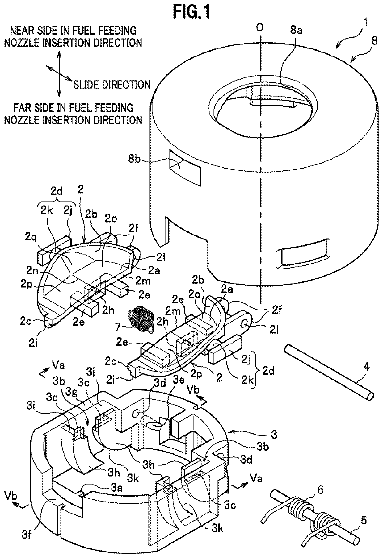
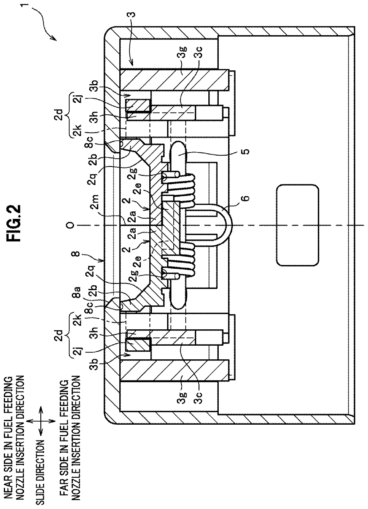
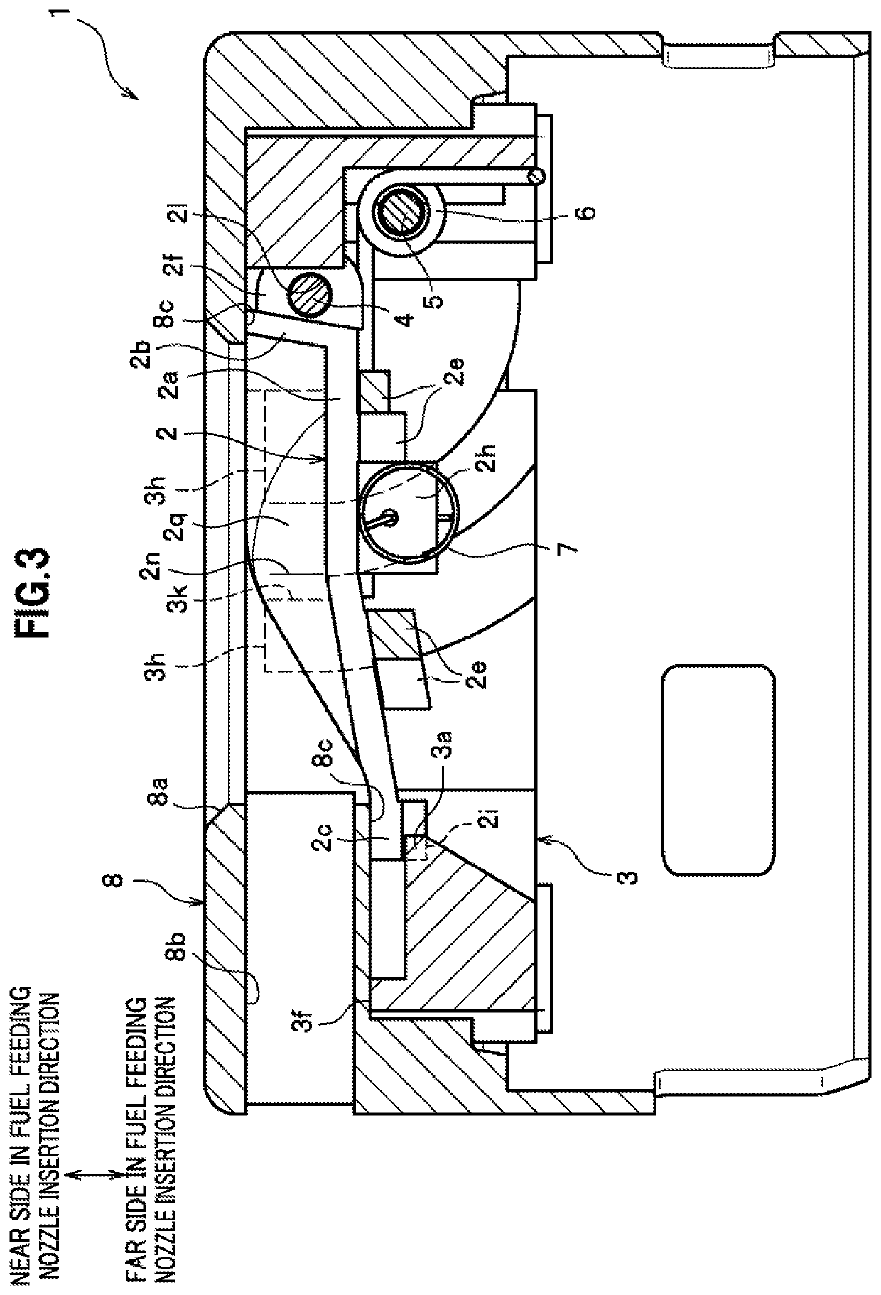
[0023]In FIGS. 1 to 4, an erroneous fuel feed prevention device 1 according to an embodiment of the present invention is a device to be provided on a fuel feed passage to block insertion of a small-diameter fuel feeding nozzle (e.g., a fuel feeding gun for gasoline) and permit insertion of a large-diameter fuel feeding nozzle (e.g., a fuel feeding gun for light oil). As illustrated in FIG. 1, the erroneous fuel feed prevention device 1 mainly includes paired flaps 2, 2, a bracket 3, a turn shaft part 4, a spring shaft part 5, a first biasing member 6, a second biasing member 7, and a housing 8.

[0024]The paired flaps 2, 2 are valves that open and close the fuel feed passage. The shapes of the paired flaps 2, 2 are substantially line-symmetric about an axis O which is the center of the fuel feed passage. The flaps 2 are slidable in radial directions of the fuel feed passage and are turnable in the direction of insertion of an fuel feeding nozzle. The directions in which the flaps 2 sl...


PUM


Abstract

An erroneous fuel feed prevention device includes paired flaps having a surface slanted relative to a direction of insertion of a fuel feeding nozzle. A turn shaft part, a support hole, and paired extension portions are provided. A first biasing member is configured to bias flaps of the paired extension portions to turn in a closing direction. A first restriction portion and a second restriction portion are configured to restrict the flaps from turning in an opening direction. While slanted surfaces are pressed by the fuel feeding nozzle, each of the flaps slide outward in radial directions of the fuel feed passage to release turning restriction states of the first restriction portion and the second restriction portion, and after the release, the flaps turn in an integrated manner with the extension portions being in contact with the respective other flaps.

Description

TECHNICAL FIELD[0001]The present invention relates to an erroneous fuel feed prevention device.BACKGROUND ART[0002]There is known an erroneous fuel feed prevention device to be provided on a fuel feed passage in a vehicle such as an automobile to block insertion of a small-diameter fuel feeding nozzle and permit insertion of a large-diameter fuel feeding nozzle. For example, Patent Literature 1 describes a technique for blocking or permitting insertion of a fuel feeding nozzle using paired flaps (shutter members) that open from and close at the center of a fuel feed passage.[0003]A long bearing hole is formed in each flap. A turn shaft member provided to a bearing bracket portion of a housing engages with the bearing hole, and thus the flap is turnable and is slidable in a radial direction of the fuel feed passage.CITATION LISTPatent Literature[0004]Patent Literature 1: Japanese Patent No. 5385288SUMMARY OF INVENTIONTechnical Problem[0005]However, since the flaps in the technique of...

Claims


Application Information

Patent Timeline
Patent Type & Authority Patents(United States)
IPC IPC(8): B60K15/04B67D7/34
CPCB60K15/04B67D7/344B60K2015/0483B60K2015/0461
Inventor HIROHARA, TAKESHIKIM, DAESUNG
Owner YACHIYO IND CO LTD
Why Eureka
Try Eureka