
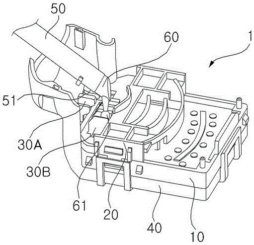
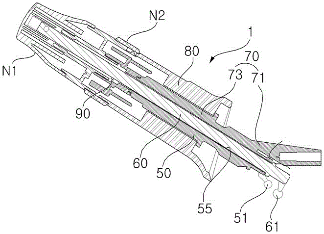
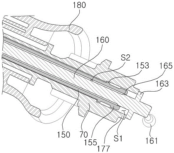
The multi-function switch assembly at the bottom left side of the steering wheel

A multi-functional switch and steering wheel technology, applied in electric switches, vehicle parts, vehicle cleaning, etc., can solve problems affecting the quality of consumers' perceptual evaluation, reduction of reset force, and product joint problems, so as to reduce operation failure and improve Restoring force and interference minimization effect

Inactive Publication Date: 2016-08-17
SUZHOU RUIYAN ELECTRONICS TECH CO LTD +1
View PDF4 Cites 0 Cited by
  • Summary
  • Abstract
  • Description
  • Claims
  • Application Information

AI Technical Summary

Problems solved by technology

[0010] Yet, one implementation example of the automobile multifunction switch assembly of prior art, in order to prevent the front end portion of the first handle arm 60 from swimming in the length direction, it is installed close to the outer surface of the front end portion of the second handle arm 50, and Interference, so there is a problem that the return force of the second rotary knob decreases when the second rotary knob is turned as the first rotary knob N1 is rotated
[0011] As mentioned above, the reduction of the reset force of the second rotary knob 50 not only affects the quality of consumers' emotional evaluation, but also causes related problems caused by product failure.

Method used


Image

  • The multi-function switch assembly at the bottom left side of the steering wheel
  • The multi-function switch assembly at the bottom left side of the steering wheel
  • The multi-function switch assembly at the bottom left side of the steering wheel

Examples


Embodiment Construction

[0023] The specific implementation manners of the present invention will be described in further detail below in conjunction with the accompanying drawings of preferred embodiments, so that the advantages and features of the technical solution of the present invention can be more easily understood and mastered. However, the present invention is not limited to the embodiments shown below, but can be embodied in various forms. This implementation example is only to show the present invention more completely, so that those with ordinary knowledge in the technical field of the present invention can fully understand the scope of the present invention, and it is defined according to the scope of the application of the present invention. The reference signs mentioned throughout the detailed description refer to the same constituent element.

[0024] An implementation example of the multifunctional switch assembly at the left bottom of the automobile steering wheel of the present inve...


PUM


Abstract

The invention discloses a multifunctional switch assembly at the left bottom of the steering wheel of an automobile, which includes two parts: an insulating cover and a handle body, wherein the insulating cover is provided with two contact terminals for generating specified electrical signals, and the handle body is provided with Two rotary knobs, two handle arms that are rotated in conjunction with each rotary knob and whose ends respectively abut against the contact terminals, and a connecting portion that guides the ends of the two handle arms to rotate, and the first handle arm is axially disposed through the second Inside the handle arm. In particular, the two handle arms are provided with a spacer cavity on the overlapping section and between the exposed end of the first handle arm and the end of the second handle arm. By applying the multifunctional switch assembly solution of the present invention, the interference between the two handle arms is minimized by improving the end structure of the handle arms, and the reset force of the second handle arm is particularly improved, which can reduce the cost of the switch assembly. Operation failure phenomenon.

Description

technical field [0001] The present invention relates to an automobile multifunctional switch assembly, more specifically, the present invention relates to a new type of switch assembly that minimizes the operation interference between two handle arms in the multifunctional switch assembly at the left bottom of the automobile steering wheel. Background technique [0002] In general, when driving at night or in areas with narrow vision and darkness such as foggy areas, in order to turn on and off the headlights, or when it snows or rains while the vehicle is running, in order to adjust the windshield wiper The wiper ensures the driver's front sight and rear sight, and the car multi-function switch assembly is installed on the car. [0003] As shown in the figure, the automobile multifunction switch assembly 1 of the prior art has a handle body 80 extending in the longitudinal direction on the side of the steering wheel. The movement of the car's headlights and wipers. [000...

Claims


Application Information

Patent Timeline
Patent Type & Authority Patents(China)
IPC IPC(8): H01H25/04
CPCH01H25/04B60Q1/1484B60S1/08H01H2025/045H01H2221/036
Inventor 李靑庸
Owner SUZHOU RUIYAN ELECTRONICS TECH CO LTD
Learn More