Liquid ejecting apparatus

a technology of liquid ejecting apparatus and ejector, which is applied in the direction of typewriters, printing, other printing apparatus, etc., can solve the problems of difficulty in preventing an increase in the size of the apparatus

Active Publication Date: 2020-02-11
SEIKO EPSON CORP
View PDF21 Cites 0 Cited by
  • Summary
  • Abstract
  • Description
  • Claims
  • Application Information

AI Technical Summary

Benefits of technology

[0014]Therefore, the number of the reciprocating movements of the first holding section (i.e., the number of times of leveling by the leveling section) over the medium (ejection region) can be increased by, for example, ejecting the pretreatment liquid in multipaths. Thus, the medium can be leveled effectively.
[0038]In the eleventh aspect, the cleaning section configured to clean the leveling section is provided, and contamination or the like attached to the leveling section can be removed.

Problems solved by technology

Hence, it may be difficult to prevent an increase in size of the apparatus.

Method used


Image

  • Liquid ejecting apparatus
  • Liquid ejecting apparatus
  • Liquid ejecting apparatus

Examples


example 1 (figs.1 to 7)

Example 1 (FIGS. 1 to 7)

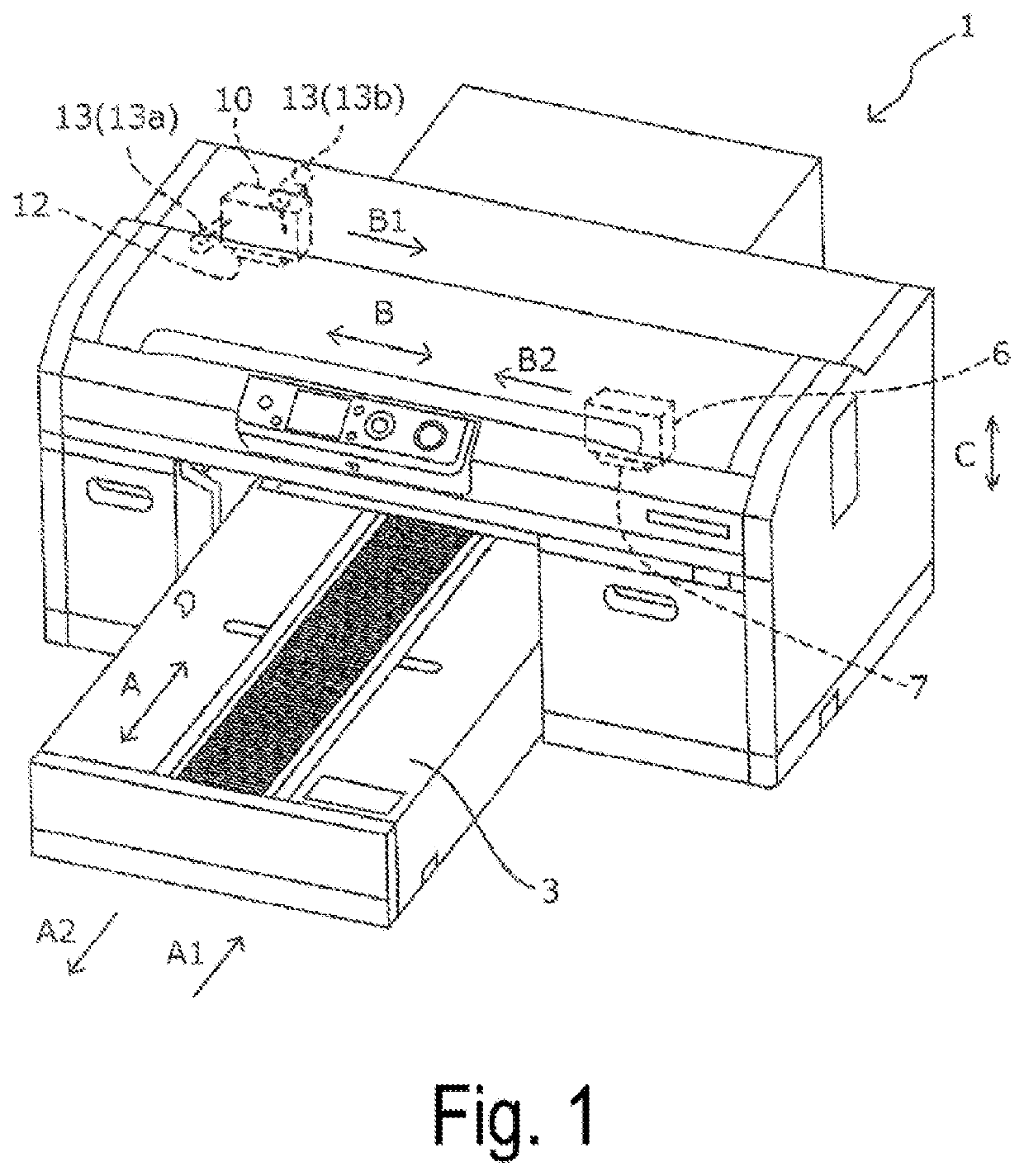
[0050]FIG. 1 is a schematic perspective view of a printing apparatus 1 according to Example 1, illustrating a state in which a medium support unit 2 is located at a printing start position.

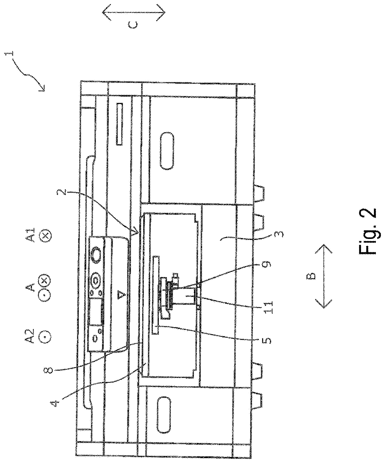
[0051]FIG. 2 is a schematic front view of the printing apparatus 1 according to Example 1.

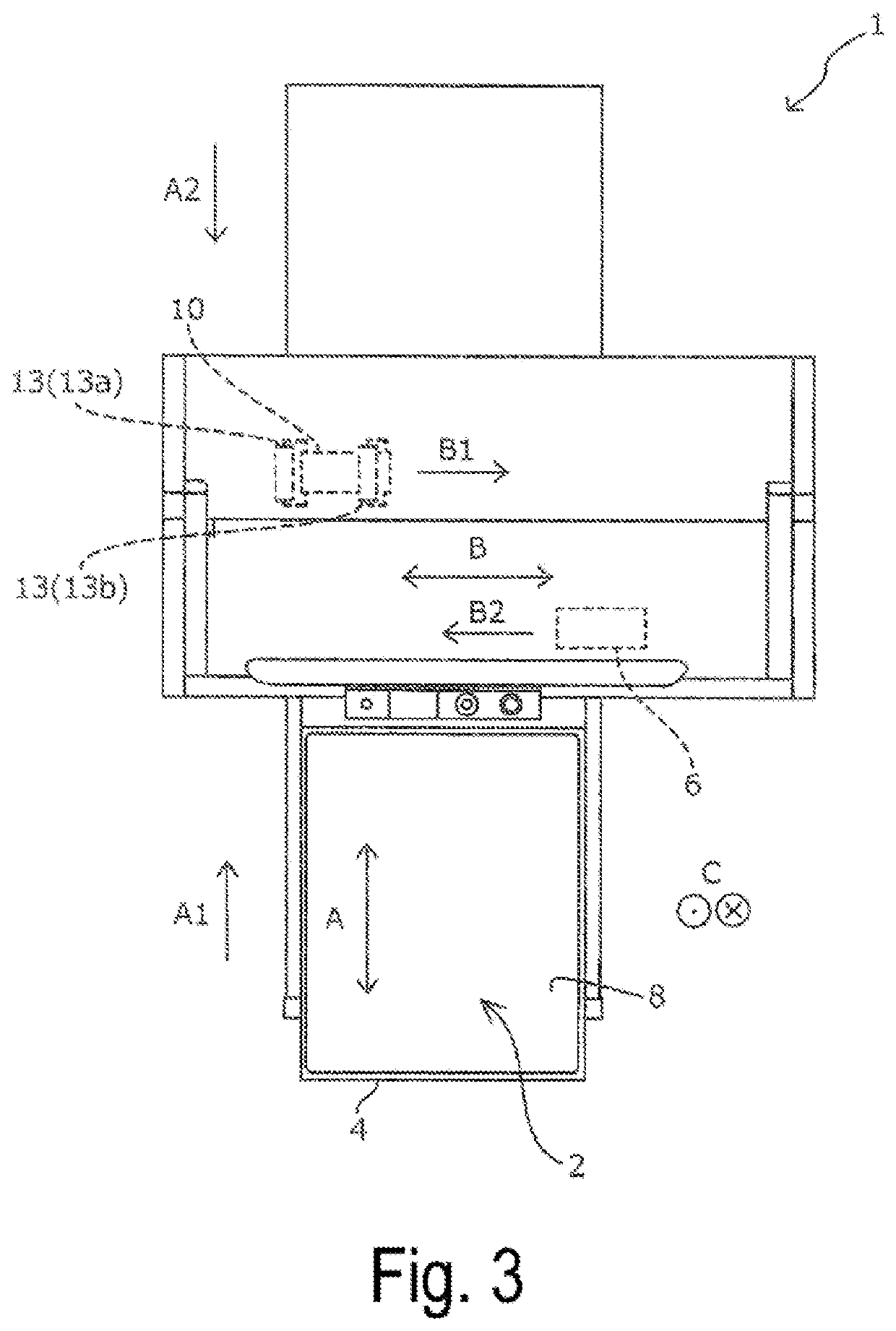
[0052]FIG. 3 is a schematic plan view of the printing apparatus 1 according to Example 1 and illustrates a state in which the medium support unit 2 is located at a medium set position.

[0053]Note that FIGS. 1 to 3 illustrate some constituent elements in a simplified manner.

[0054]The printing apparatus 1 in Example 1 includes the medium support unit 2.

[0055]The medium support unit 2 includes a tray 4 serving as a support section, and the tray 4 has a support surface 8 that supports a medium M (see FIGS. 5 and 6).

[0056]The medium support unit 2 moves in a tray movement direction A with the medium M supported on the support surface 8 of the tray 4.

[0057]The printing apparatus 1 also includ...

example 2 (fig.8)

Example 2 (FIG. 8)

[0140]FIG. 8 is a schematic front view of a carriage 10, which is a major component of a printing apparatus 1 in Example 2.

[0141]Note that the same reference signs are given to the constituent components similar to the constituent components of Example 1 and detailed description of such constituent components is omitted.

[0142]Note that the printing apparatus 1 of Example 2 is configured similarly to the printing apparatus 1 of Example 1, except for the configuration of the leveling section 13 of the carriage 10.

[0143]As illustrated in FIG. 8, the leveling section 13 of Example 2 includes a first leveling section 13c and a second leveling section 13d.

[0144]The first leveling section 13c and the second leveling section 13d each include a roller-shaped contact member 22, an attachment section 23 of the roller-shaped contact member 22, and a movement section 24 capable of moving the attachment section 23 together with the contact member 22 in an attachment and detachm...

example 3 (fig.9)

Example 3 (FIG. 9)

[0150]FIG. 9 is a schematic perspective view of the printing apparatus 1 according to Example 3.

[0151]Note that the same reference signs are given to constituent components common to the constituent components of Examples 1 and 2, and the detailed description of such constituent components is omitted.

[0152]Note that the printing apparatus 1 of Example 3 is configured similarly to the printing apparatus 1 of Example 1, except that the pretreatment liquid head 12 and the print head 7 are provided on the same carriage that is a carriage 37.

[0153]The leveling section 13 of the printing apparatus 1 of Example 1 is configured similarly to the leveling section 13 of the printing apparatus 1 of Example 3.

[0154]As illustrated in FIG. 9, the carriage 37 of the printing apparatus 1 in Example 3 is capable of reciprocating in the scanning direction B.

[0155]The carriage 37 carries both the pretreatment liquid head 12 and the print head 7.

[0156]In addition, the carriage 37 inclu...


PUM


Abstract

A liquid ejecting apparatus includes a supporting section configured to support a medium; a first ejecting section capable of ejecting a pretreatment liquid onto the medium supported by the supporting section; a first holding section configured to hold the first ejecting section; and a leveling section provided on the first holding section and being capable of moving between a leveling position in contact with an ejection region to which the pretreatment liquid is ejected and a non-leveling position in non-contact with the ejection region of the medium.

Description

BACKGROUND1. Technical Field[0001]The present disclosure relates to a liquid ejecting apparatus.2. Related Art[0002]Liquid ejecting apparatuses in various configurations are used.[0003]An example of such a liquid ejecting apparatus is a liquid ejecting apparatus capable of applying a pretreatment liquid onto a medium, e.g., fabric, before ejecting liquid such as ink onto the medium to form an image on the medium.[0004]For example, JP-A-2015-183339 discloses a recording apparatus (liquid ejecting apparatus) including an ejecting section serving as an image forming ejecting section capable of ejecting ink to form an image onto a recording medium (medium), and a pretreatment section capable of applying the pretreatment liquid onto the medium.[0005]For instance, a medium such as fabric includes fluff in some cases, and the medium is sometimes leveled after the pretreatment liquid is applied onto the medium and before an image is formed on the medium.[0006]The recording apparatus disclos...

Claims


Application Information

Patent Timeline
Patent Type & Authority Patents(United States)
IPC IPC(8): B41J11/00B41J3/407B41J29/17B41J2/01
CPCB41J3/4078B41J11/0015B41J11/0005B41J29/17B41J11/007B41J2/01
Inventor HAMADA, NOBUHIKO
Owner SEIKO EPSON CORP
Why Eureka
Try Eureka