Precleaner arrangement for use in air filtration; method; and, air cleaner using same

a pre-cleaner and air filter technology, applied in the field of air filtration, can solve the problems of increasing restriction across the air filter element, affecting reducing the efficiency of air filtration, so as to achieve the effect of reducing the restriction increase, and reducing the air flow ra

Active Publication Date: 2007-10-11
DONALDSON CO INC
View PDF40 Cites 41 Cited by
  • Summary
  • Abstract
  • Description
  • Claims
  • Application Information

AI Technical Summary

Benefits of technology

[0005] Such vane structures can be utilized to configure and construct preferred precleaner arrangements that: provide for a desirable level of efficiency of operation at relatively low air flow rates; and, provide for a preferred opening to reduce restriction increase, under higher air flow conditions.

Problems solved by technology

The service interval is generally related to the time of operation it takes for the filter element to become sufficiently loaded with dust or other material such that the restriction across the air filter element, and thus across the air cleaner, is undesirably increased.
That is, as material is loaded onto the filter element during the filtering operation, restriction across the air filter increases.
This causes restriction.
However, larger serviceable filter elements require more space.
Especially with vehicles in which the air cleaner is to be contained under the hood or within an engine compartment, available space may be severely limited.
This leads to limitation on the size and shape of space available for containing the air cleaner.
Ultimately, the amount of space available to accommodate vane axial length and outer size in a precleaner, may be somewhat limited.
Of course a price for this lower restriction, under high flow operating conditions, is less efficiency of operation for the precleaner 1.
The material from which the flexible portions of the vanes are made will also be chosen, such that the air flow increases beyond a selected point, the flexible portions will tend to bend downstream, opening the precleaner air flow for less increase in restriction but also with less efficiency of precleaner performance.
However, it is not anticipated that, typically, a seal at this location will be required.

Method used


Image

  • Precleaner arrangement for use in air filtration; method; and, air cleaner using same
  • Precleaner arrangement for use in air filtration; method; and, air cleaner using same
  • Precleaner arrangement for use in air filtration; method; and, air cleaner using same

Examples


Embodiment Construction

I. General Background

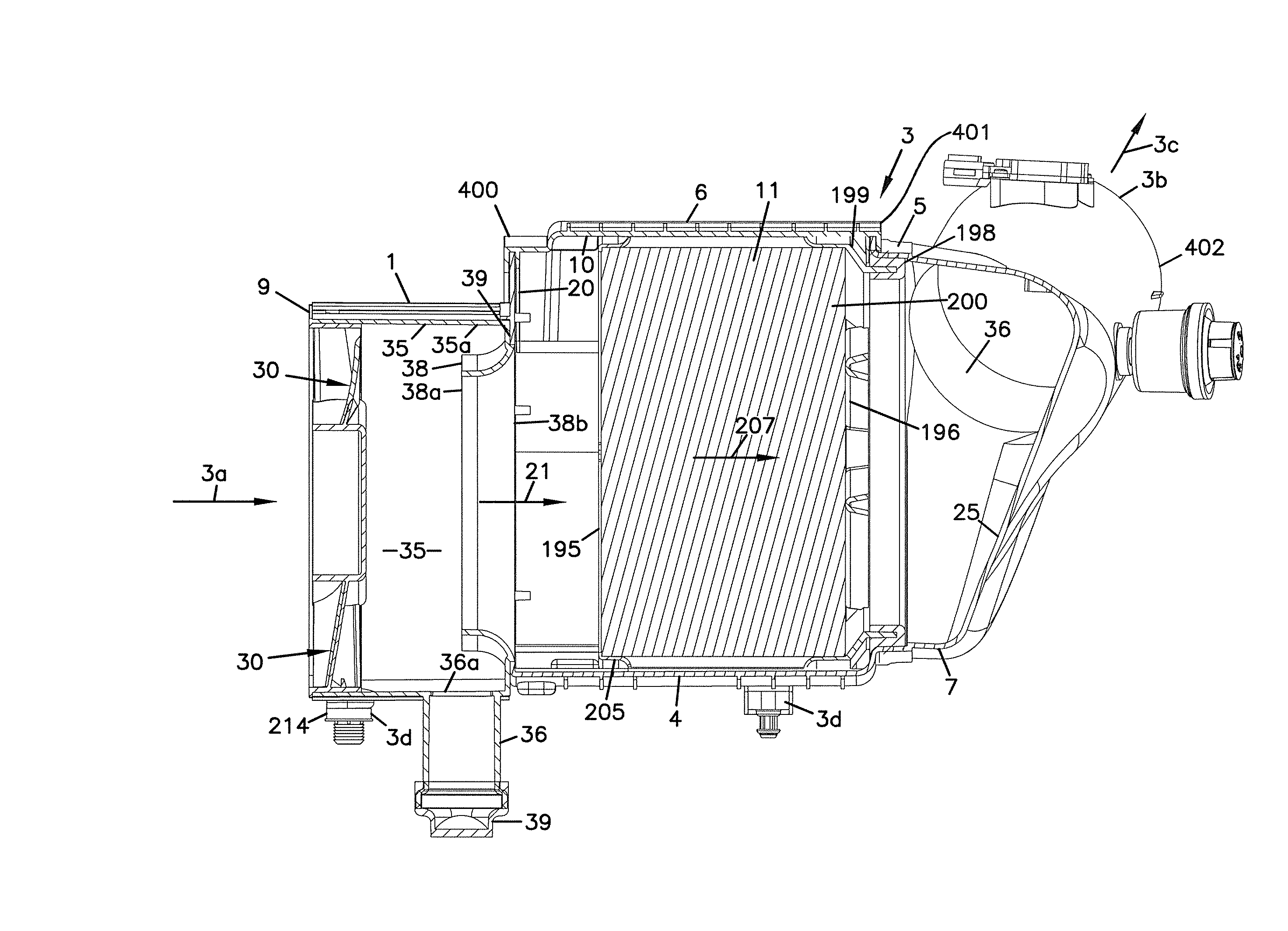
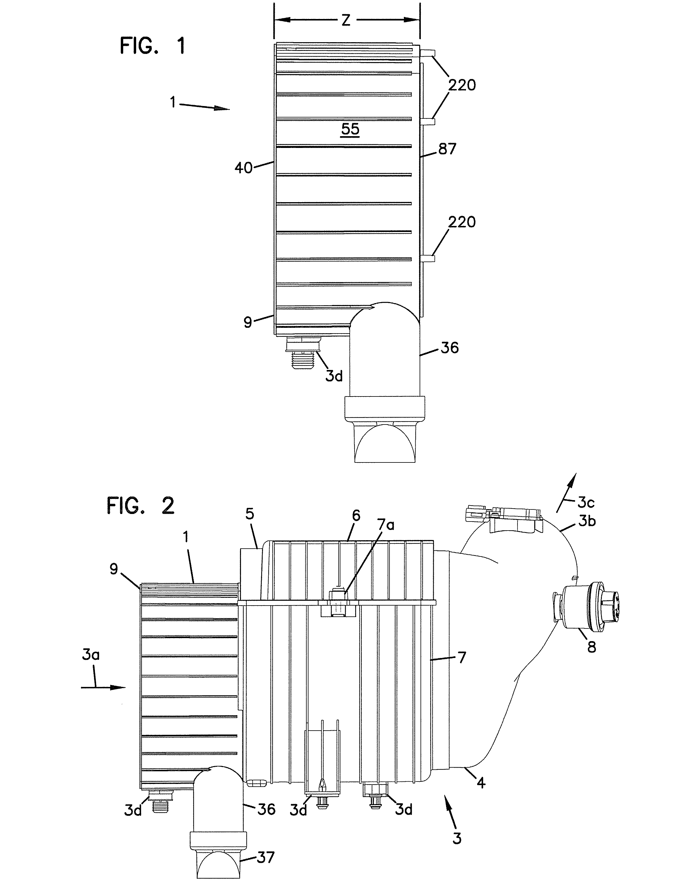
[0020] The reference numeral 1, FIG. 1, depicts a precleaner arrangement according to the present disclosure. In FIG. 2, the precleaner arrangement 1 is depicted comprising a component of an overall air cleaner assembly 3. The assembly 3 also includes main air cleaner 4, as discussed below.

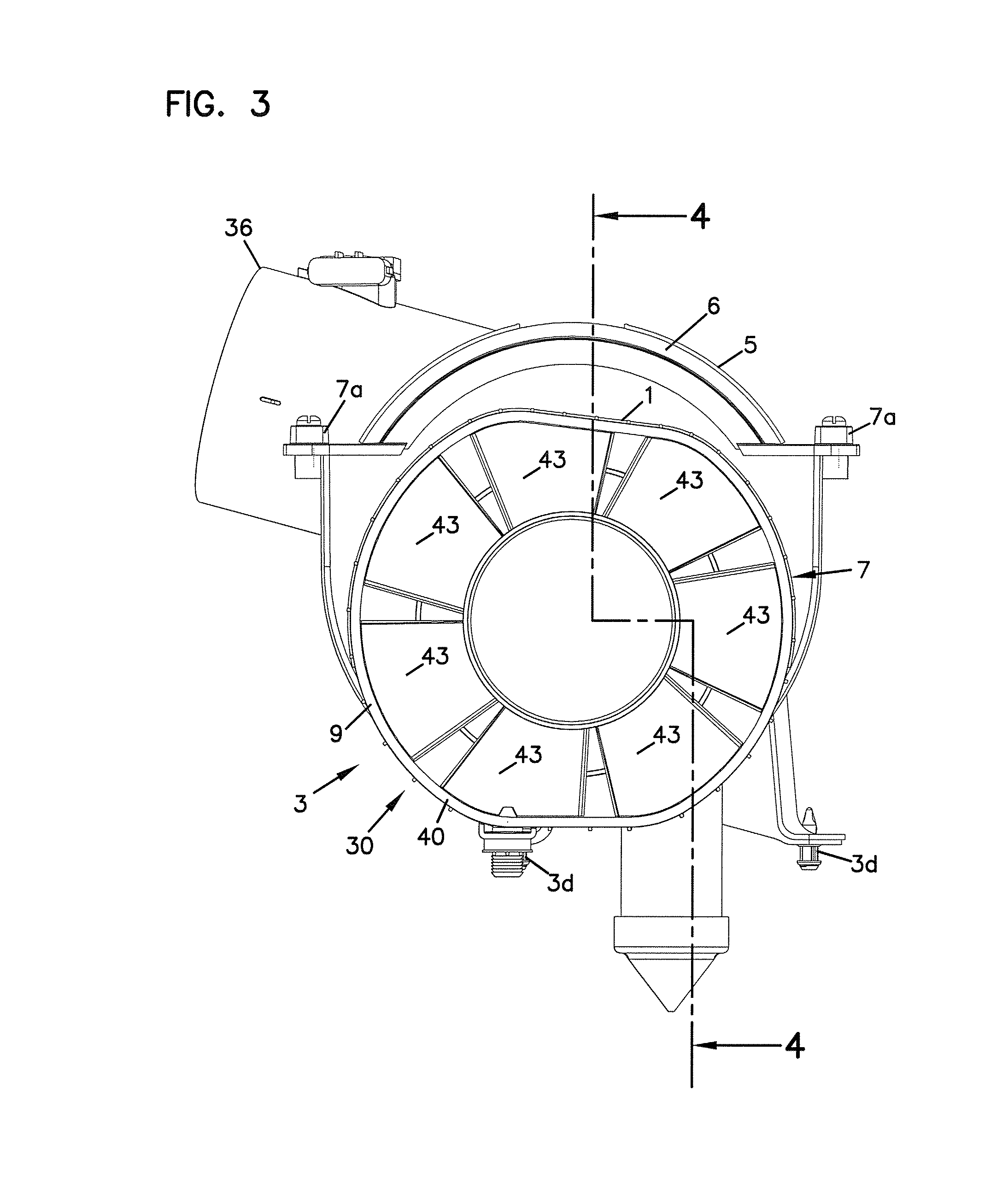
[0021] Referring to FIG. 3, the air cleaner assembly 3 is of the type typically used for filtering engine intake air for internal combustion engines. For example, the air cleaner assembly 3 can comprise an air cleaner for use with a vehicles such as trucks or tractors. As an example, the precleaner could be used with class 2-class 4 trucks, such as pickup trucks, SUVs, tow trucks, and delivery trucks, although many other applications are possible.

[0022] In general, such air cleaners include a housing 5 having, positioned therein, a serviceable air filter or air filter element, not shown in FIG. 2. By the term “serviceable” in this context, it is meant that the air filter ele...


PUM

PropertyMeasurementUnit
projection angleaaaaaaaaaa
air flow rateaaaaaaaaaa
distanceaaaaaaaaaa

Abstract

A precleaner arrangement for use in separating a portion of entrained material in air from air entering an air cleaner, is provided. The precleaner arrangement includes a vane structure positioned to direct air into a circular or cyclonic pattern, to facilitate material separation. The vane structure includes one or more adjustable air deflection vanes. Each adjustable air deflection vane is constructed: to have a first position under no air flow or low air flow rate conditions; and, to deflect to import a more open, lower restriction, orientation under increased air flow rates. Preferred precleaner arrangement constructions, assemblies utilizing in the precleaner arrangement and methods are described.

Description

FIELD OF THE INVENTION [0001] The present disclosure relates to air filtration. A typical application is in air cleaner arrangements to be used for air filtration, for example filtration of intake air for internal combustion engines. The invention particularly concerns advantageous features of precleaner assemblies for air cleaner arrangements, which provide for a precleaning of dust or other material from the air, prior to the air being passed through filter media within an air cleaner. BACKGROUND [0002] Gas streams often carry material entrained (for example dust or moisture) therein. In many instances, it is desirable to remove some or all of the entrained material from a gas flow stream. For example, air intake streams to engines for motorized vehicles, construction equipment or for power generation equipment, often include moisture or particulate material therein. The particulate material, should it reach the internal workings of the various mechanisms involved, can cause subst...

Claims


Application Information

Patent Timeline
Patent Type & Authority Applications(United States)
IPC IPC(8): B01D49/00B01D50/00B29C45/00B01D45/16F02M35/022F02M35/024
CPCB01D45/16B01D46/0045F02M35/024B01D50/002F02M35/022B01D46/525B01D50/20
Inventor XU, JIANGIESEKE, STEVEN SCOTTBARRIS, MARTY A.
Owner DONALDSON CO INC
Why Eureka
Try Eureka