Check patentability & draft patents in minutes with Patsnap Eureka AI!

Probe seat of vertical probe device

a technology of vertical probe and probe seat, which is applied in the direction of measuring device, electrical testing, instruments, etc., can solve the problem of reaction force being liable to bend the probe seat, and achieve the effect of improving rigidity

Active Publication Date: 2020-02-11
MPI CORP
View PDF8 Cites 0 Cited by
  • Summary
  • Abstract
  • Description
  • Claims
  • Application Information

AI Technical Summary

Benefits of technology

[0007]The present invention has been accomplished in view of the above-noted circumstances. It is an objective of the present invention to provide a probe seat of a vertical probe device, which has improved rigidity so as to avoid bending thereof.
[0009]As a result, because of having the at least one reinforcing die, the probe seat of the present invention has improved rigidity so as to avoid bending thereof. In particular, the at least one reinforcing die may be configured having a shape in substantial complement with the shape of the at least one through trough for bringing the probe seat relatively higher rigidity. For the way of fixedly disposing the at least one reinforcing die in the at least one through trough, a way of fixing the at least one reinforcing die on the lower die by means of at least one screw may, but not limited to, be used.
[0010]Preferably, at least one side of the through trough of the middle die may be protruded with a reinforcing block. The reinforcing block of the middle die may be fixed on the lower die by means of at least one screw. In this way, the reinforcing block can further increase the rigidity of the probe seat. More preferably, the through trough of the middle die may have two reinforcing blocks opposite to each other; this means two opposite sides of the through trough each are protruded with one reinforcing block; in this way, the probe seat has even higher rigidity.
[0011]Preferably, the lower die may have a plurality of protrusions located in the through trough of the middle die; the at least one reinforcing die is fixed on the protrusions by means of screws. More preferably, the protrusions may include two side protrusions located at two opposite sides of the through trough of the middle die respectively. Besides, two opposite sides of the through trough of the middle die may be protruded with two reinforcing blocks respectively, and the protrusions may include a middle protrusion located between the two reinforcing blocks. In this way, the protrusions can further increase the rigidity of the probe seat, and have the function of positioning the middle die on the lower die. Besides, the middle protrusion has a supporting function at the center of the through trough having a wide span, thereby bringing the probe seat relatively higher rigidity.
[0012]Preferably, the probe seat may have a plurality of detection areas, each of which is arranged corresponding in position to a device under test; the aforesaid reinforcing blocks and the middle protrusion may be located between two adjacent detection areas. In other words, the probe seat may serve as a multi-DUT probe head; in such condition, the aforesaid reinforcing die, reinforcing block and protrusion are also effective in increasing the rigidity of the probe seat, and the aforesaid reinforcing blocks and the middle protrusion have a supporting function to a place between two adjacent detection areas which are quite distanced from each other, thereby further increasing the rigidity of the probe seat.
[0013]Preferably, the probe seat may have a plurality of probe installation areas, each of which has an upper die, a reinforcing die and a through trough; the lower die and the middle die are shared by the probe installation areas. In other words, the probe seat can be the combination of multiple upper dies and multiple reinforcing dies with a single middle die and a single lower die; such arrangement is also effective in increasing the rigidity of the probe seat.

Problems solved by technology

Therefore, when the numerous probes disposed in the probe seat do the probing action at the same time, the reaction force is liable to bend the probe seat.

Method used


Image

  • Probe seat of vertical probe device
  • Probe seat of vertical probe device
  • Probe seat of vertical probe device

Examples


Embodiment Construction

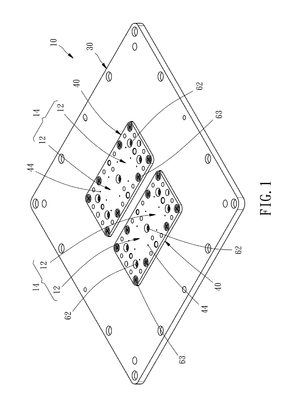
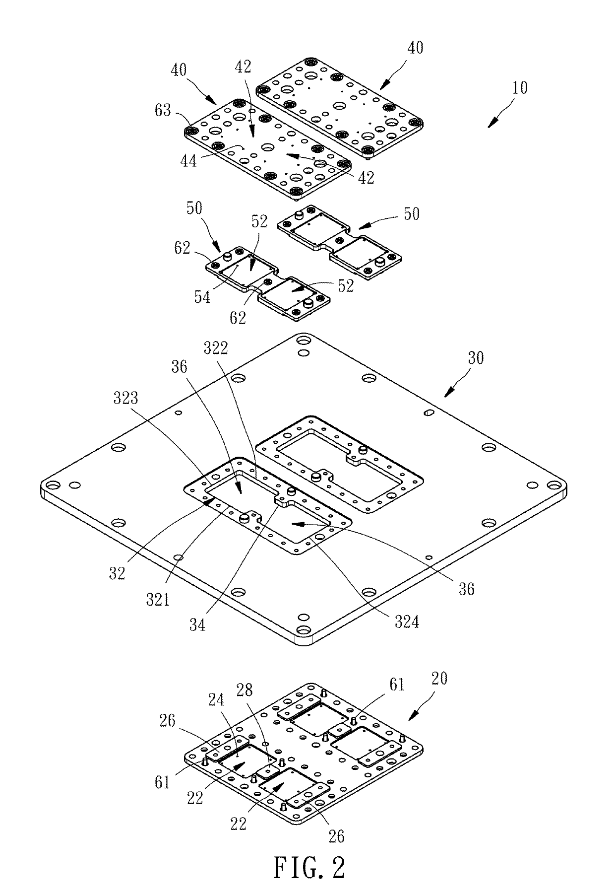
[0022]Referring to FIGS. 1-8, a probe seat 10 of a vertical probe device according to a preferred embodiment of the present invention primarily includes a lower die 20, a middle die 30, two upper dies 40, and two reinforcing dies 50.

[0023]In this embodiment, the probe seat 10 is adapted for being used in a multi-DUT probe head for testing a plurality of DUTs at the same time. Specifically speaking, the probe seat 10 has four detection areas 12 as shown in FIG. 1. Each of the detection areas 12 is arranged corresponding in position to a DUT (not shown). When the detection areas 12 of the probe seat 10 are all equipped with probes (not shown), the probe device with such probe seat and probes is capable of testing four DUTs at the same time. However, the probe seat of the present invention is not limited to be the one adapted for testing a plurality of DUTs at the same time, as shown in this embodiment. In other words, the probe seat of the present invention may have only one detection...


PUM


Abstract

A probe seat of a vertical probe device includes a lower die, a middle die fixed on the lower die, at least one upper die fixed on the middle die, and at least one reinforcing die fixedly disposed in at least one through trough of the middle die. The lower die has lower probe holes located below the through trough, such that probes are be inserted through the lower probe holes respectively and inserted through the through trough. The at least one upper die has upper probe holes located above the through trough for the probes to be inserted therethrough. The at least one reinforcing die has middle probe holes for the probes to be inserted therethrough. As a result, the probe seat has improved rigidity to avoid bending.

Description

BACKGROUND OF THE INVENTION[0001]1. Field of the Invention[0002]The present invention relates generally to a probe device of a probe card and more particularly, to a probe seat of a vertical probe device.[0003]2. Description of the Related Art[0004]Upon testing semiconductor chips, a testing equipment is electrically connected with devices under test (hereinafter referred to as the “DUTs”) through a probe card, so that the testing equipment can obtain the testing results of the DUTs by means of signal transmission and analysis. The conventional probe card is usually composed of a circuit board and a probe device, or further includes a space transformer disposed between the circuit board and the probe device. The conventional vertical probe device usually includes a probe seat, and a plurality of vertical probes penetrating through the probe seat in substantially vertical posture. The vertical probes, such as pogo pins, are arranged corresponding in positions to contact pads of the D...

Claims


Application Information

Patent Timeline
Patent Type & Authority Patents(United States)
IPC IPC(8): G01R1/073G01R1/04
CPCG01R1/04G01R1/07371G01R1/07314
Inventor CHEN, TSUNG-YICHEN, SHIH-SHIN
Owner MPI CORP
Features
  • R&D
  • Intellectual Property
  • Life Sciences
  • Materials
  • Tech Scout
  • Unparalleled Data Quality
  • Higher Quality Content
  • 60% Fewer Hallucinations
Learn More