Display tray with support column and apertures

a technology of support column and display tray, which is applied in the field of display tray, can solve the problems of excessive materials, inconvenient product access, and laborious manufacturing, assembling or conversion of other displayable shipping containers, and achieve the effect of convenient and efficient display

Active Publication Date: 2020-02-18
MARS INC
View PDF33 Cites 2 Cited by
  • Summary
  • Abstract
  • Description
  • Claims
  • Application Information

AI Technical Summary

Benefits of technology

[0012]The instantly described display tray can be assembled from a continuous source of the same material. These display trays are stackable, i.e., two or more trays can be stacked onto each other to provide a convenient and efficient display for consumer products.

Problems solved by technology

Such convertible containers represent a challenge in that they must be readily convertible into a form presentable to customers, while at the same time maintaining certain shipping performance characteristics, suitable for the shipment of non-self-supporting or even fragile products.
For example, prior displayable shipping containers often are either lacking in the necessary shipping performance characteristics or, in order to provide such performance, have structural elements that remain in position after converting to a display configuration that make access to the product inconvenient.
Other displayable shipping containers are labor intensive to manufacture, assemble, or convert.
And still other containers require excessive materials or, in some cases, extraneous components (e.g., a tie or a wrap) to secure a lid on a body of the container.
Once converted to a display configuration, many displayable shipping containers often also include rough, unfinished, jagged, and uneven surfaces in prominent locations that are somewhat unsightly and do not provide the appeal of a neat, clean and presentable display.
Because of the industry push to minimize the amount of corrugated paperboard or other starting material used to form a container and because of the desire to display a shipping container that is free of excessive structural elements, prior displayable containers tend to be somewhat weak, and in certain situations they can deform when stacked.

Method used


Image

  • Display tray with support column and apertures
  • Display tray with support column and apertures
  • Display tray with support column and apertures

Examples


Embodiment Construction

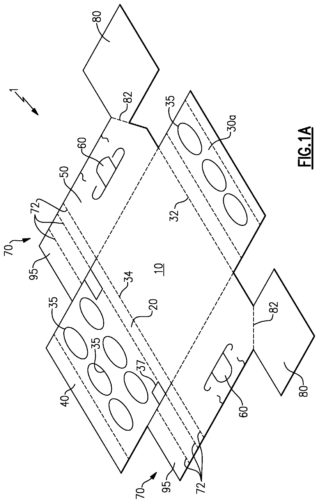
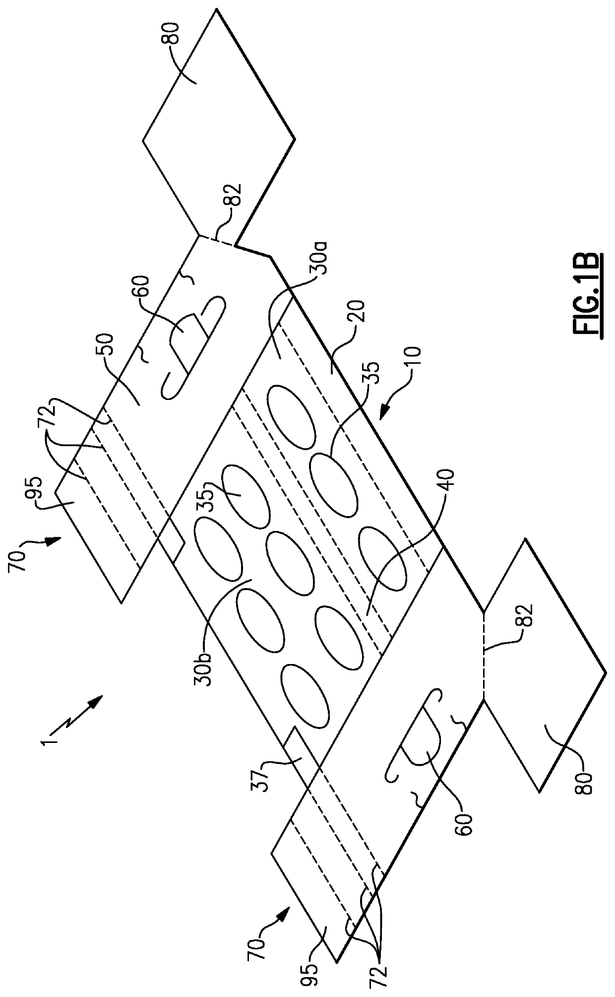
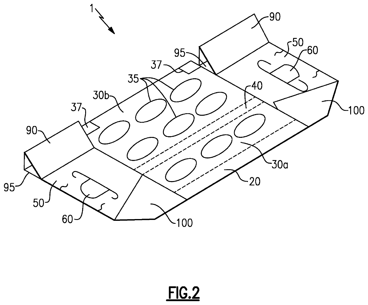
[0028]The display trays of the embodiments described herein are typically composed of corrugated paperboard, preferably with the corrugations running in a vertical direction for increased strength. As non-limiting examples, the containers may be composed of C-flute, EB-flute, E-flute or B-flute corrugated paperboard. It is to be understood that the principles of this invention could be applied to containers made of other materials, such as non-corrugated paperboards, cardboard, corrugated fiberboard, non-corrugated fiberboard, solid-fiber board, polymeric materials, and other foldable materials.

[0029]FIGS. 1-7 show illustrative, non-limiting embodiments of the present invention, setting forth an exemplary method of preparing a display tray, and the display tray apparatus formed thereby. Certain terminology is used herein for convenience only and is not to be taken as a limitation on the present invention. While the following describes certain illustrative embodiments of the present ...


PUM


Abstract

An apparatus to display packaged products that includes a base that includes a bottom segment, at least two supporting segments, and a top segment, the top segment provided with a plurality of apertures and supported at least in part by the at least two supporting segments such that the bottom segment and the top segment are generally parallel; and at least two side portions, at least one of said side portions comprising a support column, the at least two side portions being generally perpendicular to the bottom segment and the top segment. Methods of assembling the apparatus are also provided.

Description

CROSS-REFERENCE TO RELATED APPLICATIONS[0001]This application is a national stage application, filed under 35 U.S.C. § 371, of International Application No. PCT / US2015 / 045116, filed Aug. 13, 2015, which claims the benefit of GB Application No. 1414358.0, filed Aug. 13, 2014, entitled “DISPLAY TRAY WITH SUPPORT COLUMN AND APERTURES,” both of which are incorporated herein by reference in their entirety for any and all purposes.FIELD OF THE INVENTION[0002]One or more embodiments of the present invention relate to a display tray that can be used to display consumer products in a retail environment.BACKGROUND[0003]Flat sheets of corrugated paperboard, typically referred to as blanks, have been used for many years as the starting material to form containers. Corrugated paperboard can take the form of multi-layer sheet material comprised of two sheets of liner bonded to a central corrugated layer of medium. Given a basic size requirement specified by the customer, industry standards, and t...

Claims


Application Information

Patent Timeline
Patent Type & Authority Patents(United States)
IPC IPC(8): B65D5/52B65D5/486B31B50/60B65D5/50A47F5/11B65D5/20B65D5/64B65D5/44B65D5/468B65D5/42B65D5/00B31B50/74B31B50/26B31B50/81B31B50/62B31B100/00B31B120/00
CPCB31B50/74B65D5/5286B65D5/443B65D5/0045A47F5/114B31B50/60B65D5/64B65D5/5021B65D5/20B65D5/4266B65D5/4608B31B2100/00B31B50/81B31B50/62B31B50/26B31B2120/502
Inventor COOPER, DEREK
Owner MARS INC
Why Eureka
Try Eureka