Device for modulating a gas ejection section

a technology of gas ejection and ejection section, which is applied in the direction of rocket engine plants, machines/engines, jet propulsion plants, etc., can solve the problems of significantly increasing the cost of the launcher, and reducing the thrust efficiency of the thruster. achieve the effect of optimizing the thrust efficiency

Active Publication Date: 2020-02-25
ARIANEGRP SAS
View PDF9 Cites 0 Cited by
  • Summary
  • Abstract
  • Description
  • Claims
  • Application Information

AI Technical Summary

Benefits of technology

The device of the invention for modulating a gas ejection section proposes a solution that is simple, inexpensive, and compact that makes it possible to define two modes of operation for a nozzle, specifically a first mode of operation at a high rate in which the partial shutter member is axially set back from the throat of the nozzle, and a second mode of operation at a lower rate in which the member for partially shutting the throat is extended axially further relative thereto. The changeover from the first mode of operation to the second mode of operation is obtained by breaking the retaining element(s). The use of one or more breakable or fusible retaining elements in combination with a plunger and a plunger guide makes it possible to define an architecture that is inexpensive, simple, and reliable for providing nozzles of variable throat section, and to do so without significantly increasing the weight or the size of the thruster.
Also, the device of the invention for modulating a gas ejection system makes it possible to avoid using two distinct thrusters (one thruster for the acceleration or “boost” stage, and another thruster for the cruising stage), and consequently makes it possible to propose a propulsion system at low cost that can provide both rates of operation.
According to a particular characteristic of the nozzle of the invention, it is of the aerospike type, i.e. a nozzle operating without a diverging portion, thereby simultaneously reducing the cost, the weight, and the overall size of the thruster, while also making it possible to optimize the thrust of the vehicle, regardless of its altitude of operation.

Problems solved by technology

Nevertheless, having recourse to a single throat section is not appropriate for a thruster having two operating rates, typically one when operating at a high rate (acceleration) and another when operating at a lower rate (cruising), or for a thruster that is to fly at varying altitude.
Nevertheless, such a solution has the drawback of significantly increasing the cost of the launcher.
Nevertheless, although the use of a plunger provides a solution that is inexpensive and that enables a plurality of operating rates to be obtained in a single nozzle, thrust efficiencies are not optimized for those various operating rates.

Method used


Image

  • Device for modulating a gas ejection section
  • Device for modulating a gas ejection section

Examples


Embodiment Construction

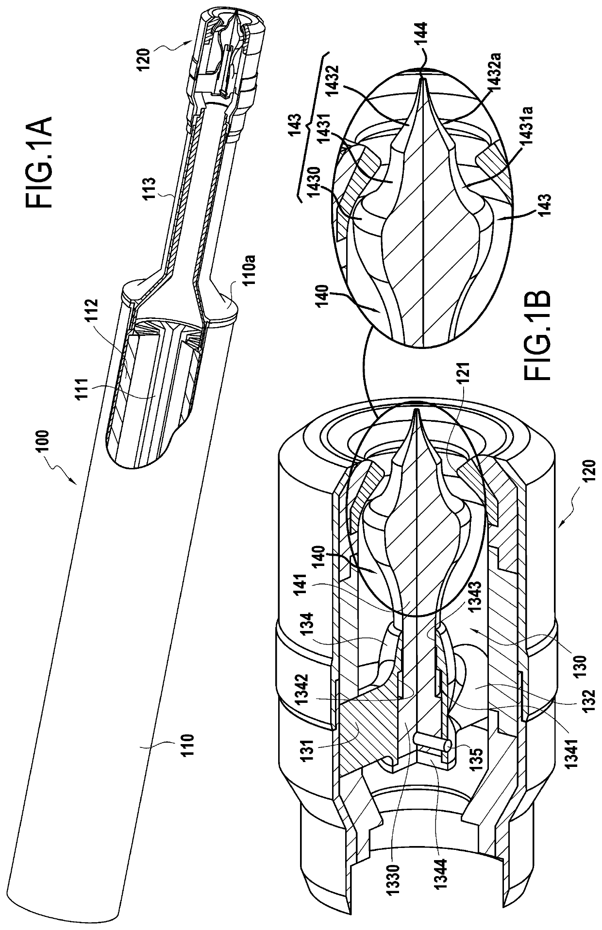
The device of the invention for modulating a gas ejection section may be used with any type of nozzle, and in particular with nozzles whether or not they include a diverging portion.

FIG. 1A shows diagrammatically and in longitudinal section the rear portion of a thruster 100 comprising a cylindrical casing 110 surrounding a combustion chamber 111 in which there is housed a block of solid propellant 112. The chamber 111 opens out through the rear end 110a of the casing 110 upstream from an “aerospike” type nozzle 120. The term “aerospike” is used herein to mean a nozzle that has practically no diverging portion and that includes a plunger of concave profile capable of emerging through its throat. In the presently described embodiment, the nozzle 128 is connected to the rear end 110a via an extender 113. Nevertheless, in a variant embodiment of a thruster of the invention, the nozzle 120 could be connected directly to the rear end of the thruster casing, i.e. without the extender 113....


PUM


Abstract

A modulator device for modulating a gas ejection section, which device is for placing in a nozzle upstream from the throat of the nozzle and includes a plunger. The plunger has both a proximal portion connected to a control guide and also a distal portion in the form of a body of revolution, the plunger being movable between a retracted position and an extended position. The plunger presents, in its distal portion, a first section of concave shape and a second section of concave shape situated downstream from the first section.

Description

BACKGROUND OF THE INVENTIONThe present invention relates to the general field of thrusters or rocket engines for delivering thrust for driving vehicles such as missiles, launchers, or indeed satellites, by using the principle of propulsion by reaction or by ejecting gas. The invention relates more precisely, but not exclusively, to the nozzles that are fitted to solid propellant thrusters.A solid propellant thruster is constituted mainly by a casing enclosing a block of propellant, an igniter, and a non-variable diverging nozzle. The block of propellant is pierced by a channel situated on the axis of the thruster, which channel serves as a combustion chamber. The igniter serves to ignite the propellant at one end of the casing, and combustion of the propellant propagates from the front towards the rear of the thruster. The propellant burns at a predefined speed, thereby producing combustion gas that is expelled via the nozzle.The throat section of the nozzles serves to regulate comb...

Claims


Application Information

Patent Timeline
Patent Type & Authority Patents(United States)
IPC IPC(8): F02K9/86F02K9/80
CPCF02K9/805F02K9/86F05D2270/303F05D2250/712F05D2270/051F05D2250/41F05D2260/36F05D2240/1281
Inventor CAUBET, PASCALLARRIEU, JEAN-MICHEL
Owner ARIANEGRP SAS
Why Eureka
Try Eureka