
Tile cutter

a tile cutter and cutting board technology, applied in the field of tile cutters, can solve the problems of reducing the portability limiting and reducing the maximum cutting capability of the tile cutter. the effect of increasing the weight and the size of the cutter

Inactive Publication Date: 2007-06-28
NANJING CHERVON IND
View PDF14 Cites 8 Cited by
  • Summary
  • Abstract
  • Description
  • Claims
  • Application Information

AI Technical Summary

Benefits of technology

[0007] The object of the present invention is to provide a tile cutter which has increased cutting capability and with good portability at the same time.
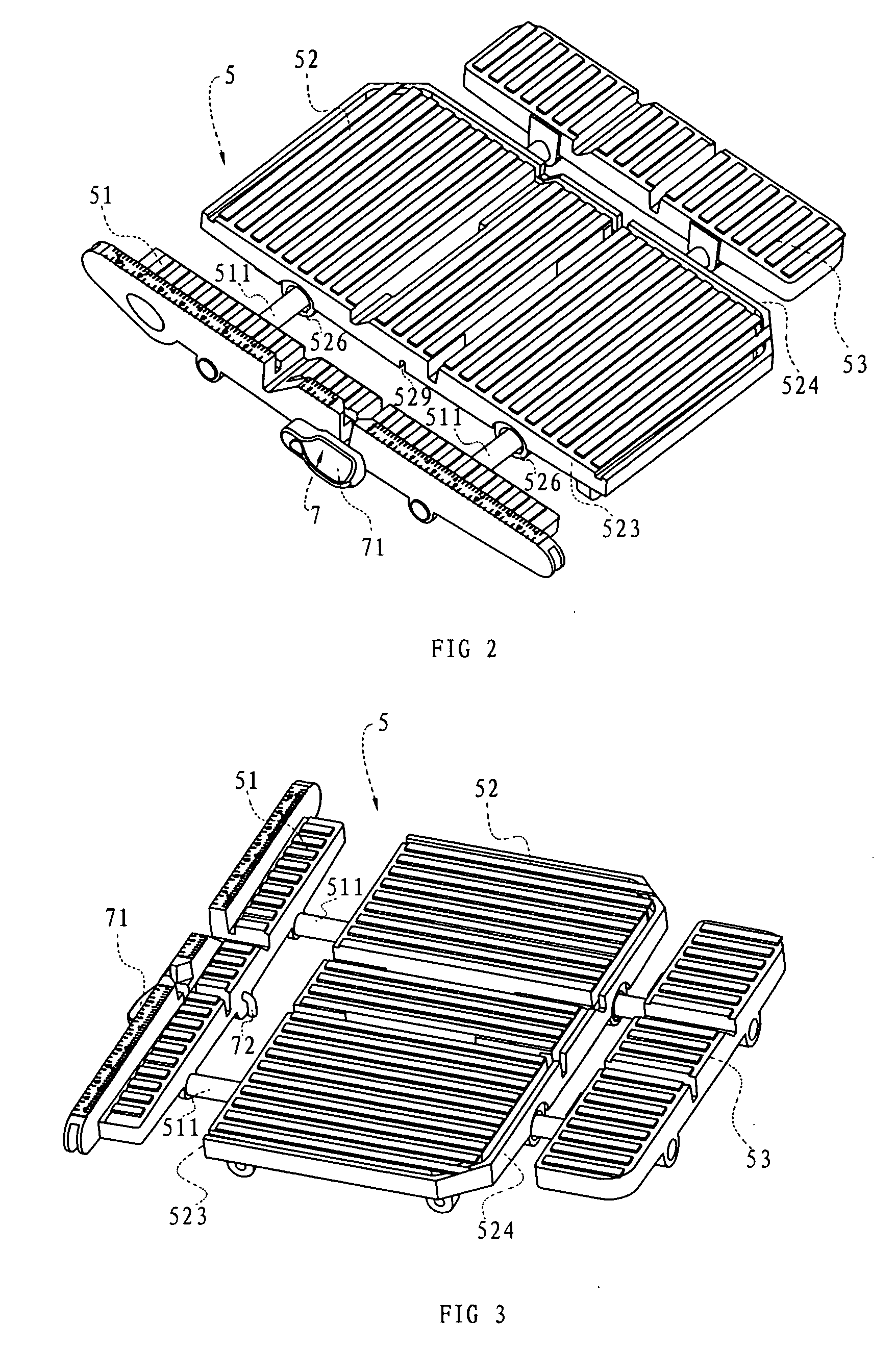
[0013] With the worktable assembly of the tile cutter according to the present present invention, an operator may conveniently change the support capability of the worktable assembly to accommodate work pieces having different sizes without increasing the weight and size of the cutter.

Problems solved by technology

However, the maximum cutting capability of the tile cutter is generally limited by the dimension of the worktable.
To overcome such disadvantage of the conventional tile cutter, there has been a tile cutter in market, wherein a rail is arranged on the base of the tile cutter and a worktable is slidably connected to the rail by a sliding bearing or wheels, while the maximum cutting capability is still limited by the length of the rail.
A common way for increasing the cutting capability is to increase the length of the rail, which results in decreasing of the portability of the tile cutter.

Method used


Image

  • Tile cutter
  • Tile cutter
  • Tile cutter

Examples


Embodiment Construction

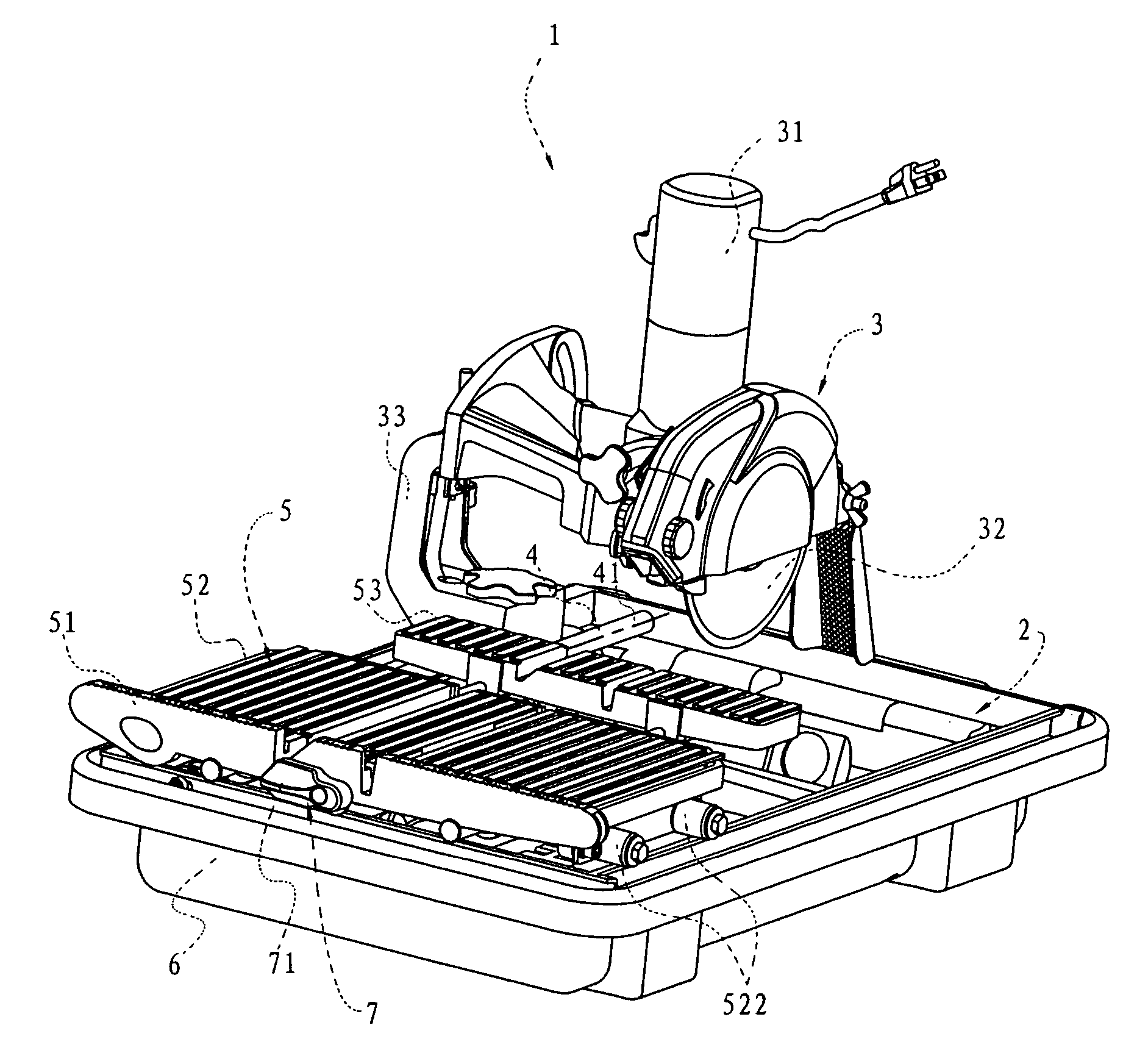
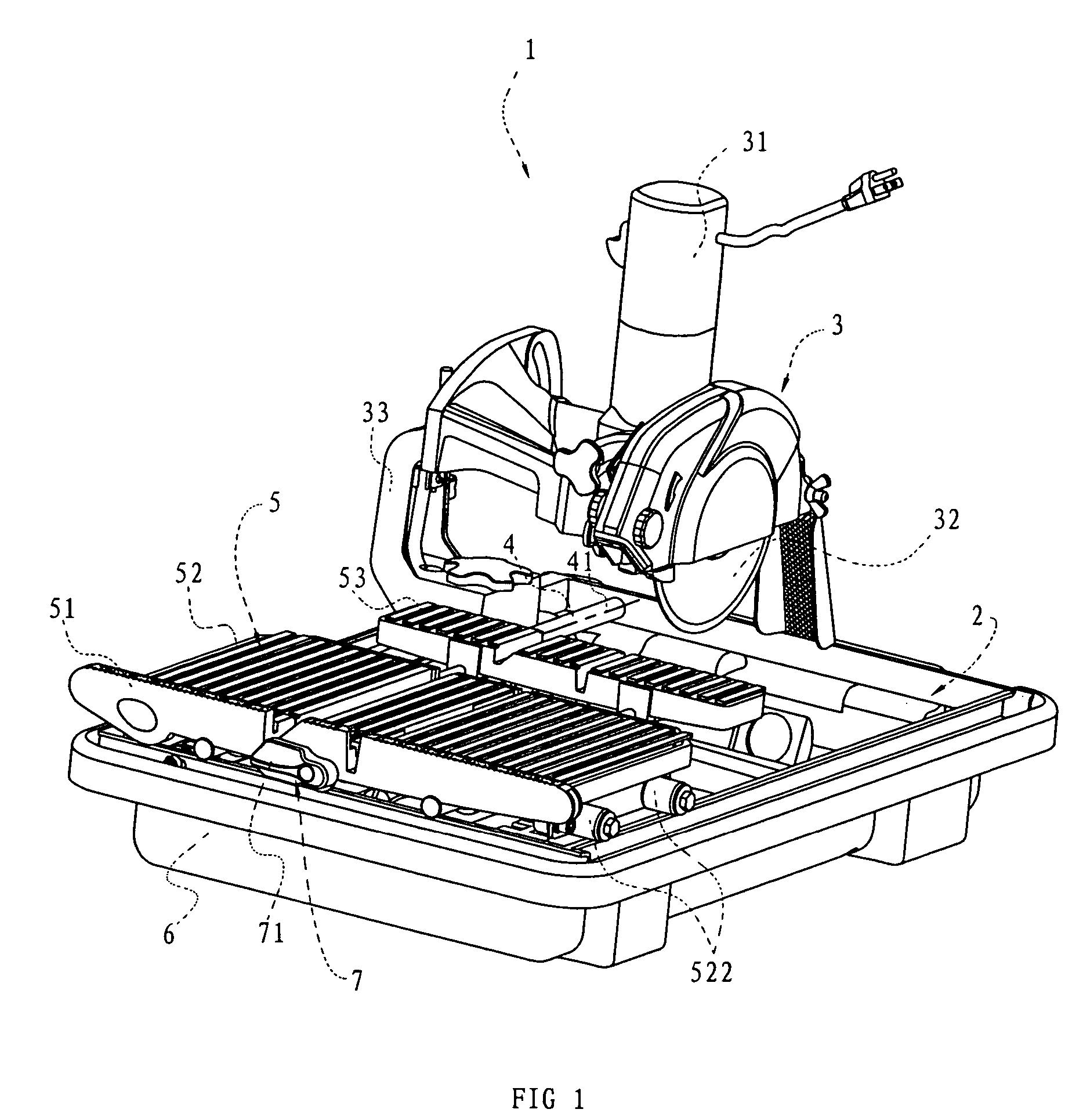
[0017] As shown in FIG. 1, a tile cutter of a preferred embodiment of the present invention comprises a support frame 2, a saw unit 3, at least one rail, and a worktable assembly 5. The support frame 2 is generally rectangular. The saw unit 3 comprises a motor 31 and a cutting element 32 driven by the motor. The saw unit 3 is installed on the support frame 2 through a C-shaped support arm. The at least one rail comprises a first rail 4. The first rail 4 has two ends fixedly mount to opposite sides of the support frame, and has a longitudinal axis 41. The longitudinal axis of the first rail 4 is parallel to the cutting direction of the cutting element 32. The tile cutter 1 may further comprise a basin 6 for supporting the support frame 2 therein. It is obvious to those skilled in the art that the support frame may have other shapes and configurations as desired, and a basin as disclosed in U.S. Pat. No. 5,676,124 can be used and to be placed in the support frame.

[0018] Referring to ...


PUM


Abstract

A tile cutter which has increased cutting capability and with good portability at the same time, comprises a support frame, a saw unit mounted on the support frame, at least one rail and a worktable assembly. The at least one rail is fixed on the support frame and comprises a longitudinal axis. The worktable assembly comprises at least a first worktable and a second worktable, support surfaces of which are in the same plane. The second worktable is slidably installed on the first rail and the first worktable is installed on the second worktable.

Description

CROSS-REFERENCE TO RELATED APPLICATIONS [0001] This application claims priority to Chinese Application No. 200520140152.8 filed Dec. 22, 2005, the entire disclosure of which is incorporated herein by reference. Priority to this application is claimed under 35 U.S.C. 119, 120 and / or 365. FEDERALLY SPONSORED RESEARCH OR DEVELOPMENT [0002] Not Applicable. TECHNICAL FIELD [0003] The present invention relates to a tile cutter, in particular to a tile cutter which can increase the cutting capability. BACKGROUND OF THE INVENTION [0004] Conventionally, to cut a tile, the tile is directly put on a worktable which is fixed relative to the cutter. However, the maximum cutting capability of the tile cutter is generally limited by the dimension of the worktable. [0005] To overcome such disadvantage of the conventional tile cutter, there has been a tile cutter in market, wherein a rail is arranged on the base of the tile cutter and a worktable is slidably connected to the rail by a sliding bearin...

Claims


Application Information

Patent Timeline
IPC IPC(8): B28D1/04
CPCB23D47/025B28D1/047Y10T83/773Y10T83/7647Y10T83/7722B28D7/04
Inventor LI, JIANGNAN
Owner NANJING CHERVON IND
Learn More