Integrated illumination assembly for symbology reader
What is AI technical title?
AI technical title is built by Patsnap AI team. It summarizes the technical point description of the patent document.
a symbology reader and integrated technology, applied in the field of illumination, can solve the problems of inability to intuitively choose bright field, dark field, direct or diffuse light, and use of highly reflective bright field illumination, so as to improve illumination performance, increase the durability of light pipes, and increase the effect of weight or siz
Inactive Publication Date: 2015-06-30
COGNEX TECH & INVESTMENT
View PDF297 Cites 4 Cited by
Summary
Abstract
Description
Claims
Application Information
AI Technical Summary
This helps you quickly interpret patents by identifying the three key elements:
Problems solved by technology
Method used
Benefits of technology
Benefits of technology
[0019]This invention overcomes the disadvantages of the prior art by providing a plurality of novel features that can be applied variously to a reader to improve the illumination performance in both dark field / direct bright field and direct diffuse types of illumination. Further features allow for increased light pipe durability without increasing weight or size and better readability of status indicators by placing such indicators in proximity to the subject and significantly enlarging to overall size of the indicator.
[0020]In one embodiment, the light pipe is constructed from durable polycarbonate for increased shock resistance. The chamfered end of the light pipe is textured or frosted to further diffuse refracted light passing through the end so as to present a more even effect. The conical / tapered diffuser within the light pipe is illuminated by a reflector with a white textured surface that reflects a plurality of rearward-directed (opposite the illumination and viewing direction) illumination sources back into the diffuser. The reflector can define a predetermined cross section that directs further light into the forwardmost, remote regions of the diffuser to generate a better overall spread of light and alleviate light and dark spotting effects. The textured surface on the chamfered light pipe end can be employed to better project indicator light. The textured surface can alternatively (or in addition) be applied to the exposed portion of the inner wall adjacent to the distal (forward) end of the pipe.
[0022]In an illustrative embodiment, the light pipe defines a polygonal (for example rectangular) cross section (with the polygon being generally defined as at least four linear or non-linear sides, joined at corners (that may be rounded) to form a (typically) non-equilateral shape. The chamfered edge on each side is at a fixed angle and thus the differing length of the North-South versus East-West sides (in the case of a rectangle), generates two different distances for convergence of dark field rays, which increases depth of field. Stated differently, the polygon (rectangle) includes at least two pairs of opposing sides and the first pair of opposing sides has a length different than the second pair of opposing sides to generate two differing-distance convergence points for dark field rays.
Problems solved by technology
Conversely, where a symbology or other subject is formed on a more-irregular surface, or is created by etching or peening a pattern directly on the surface, the use of highly reflective bright field illumination may be inappropriate.
A peened / etched surface has two-dimensional properties that tend to scatter bright field illumination, thereby obscuring the acquired image.
Often, the choice of bright field, dark field, direct or diffuse light is not intuitive to user for many types of surfaces and / or the particular angles at which the reader is directed toward them.
However, acrylic tends to shatter easily in response to impact.
This may limit the life and endurance of a handheld reader (particularly a cordless / wireless model) that is expected to occasionally drop and strike a hard floor, perhaps against the light pipe.
While the light pipe could be armored with cushioning and external housings, this undesirably increases production costs, weight, obtrusiveness and may optically obscure the pipe.
Also, where a conical diffuser is employed to provide an overall source of direct diffuse illumination, prior art devices are limited in their ability to spread light from a few individual illumination sources (LEDs, for example) throughout the diffuser surface, and then onto the subject as diffuse light.
Adding further illumination sources to the diffuse section may be limited both by space and the relative cost of illumination sources, particularly where relatively costly blue-colored LEDs are employed.
However, in a production environment, small, rear-mounted or top-mounted indicators may be overlooked or present a distraction while the user tries to focus on the surface being read.
Method used
Image
Click on the blue label to locate the original text in one second.
Reading with bidirectional positioning of images and text.
Examples
Embodiment Construction
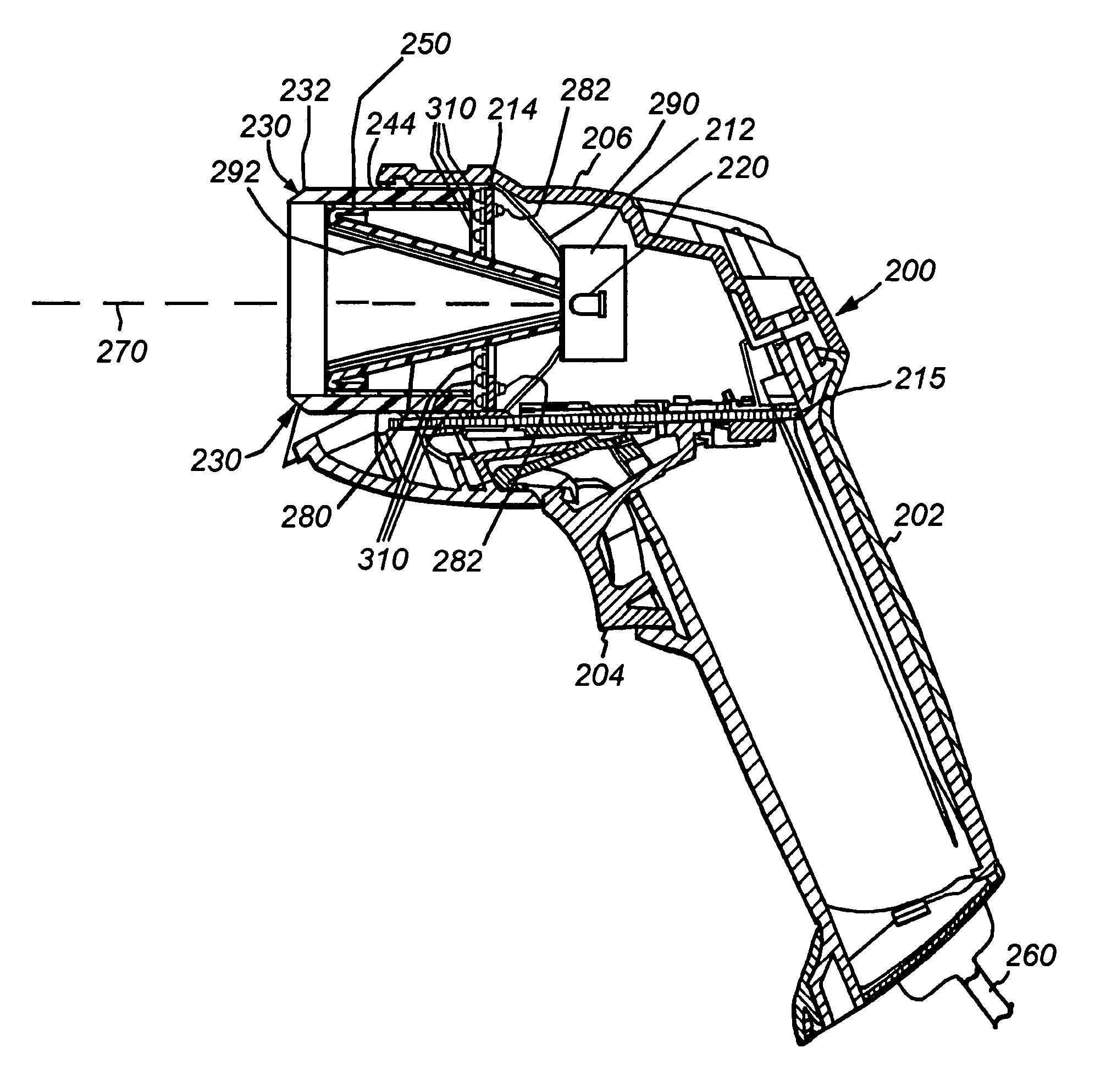
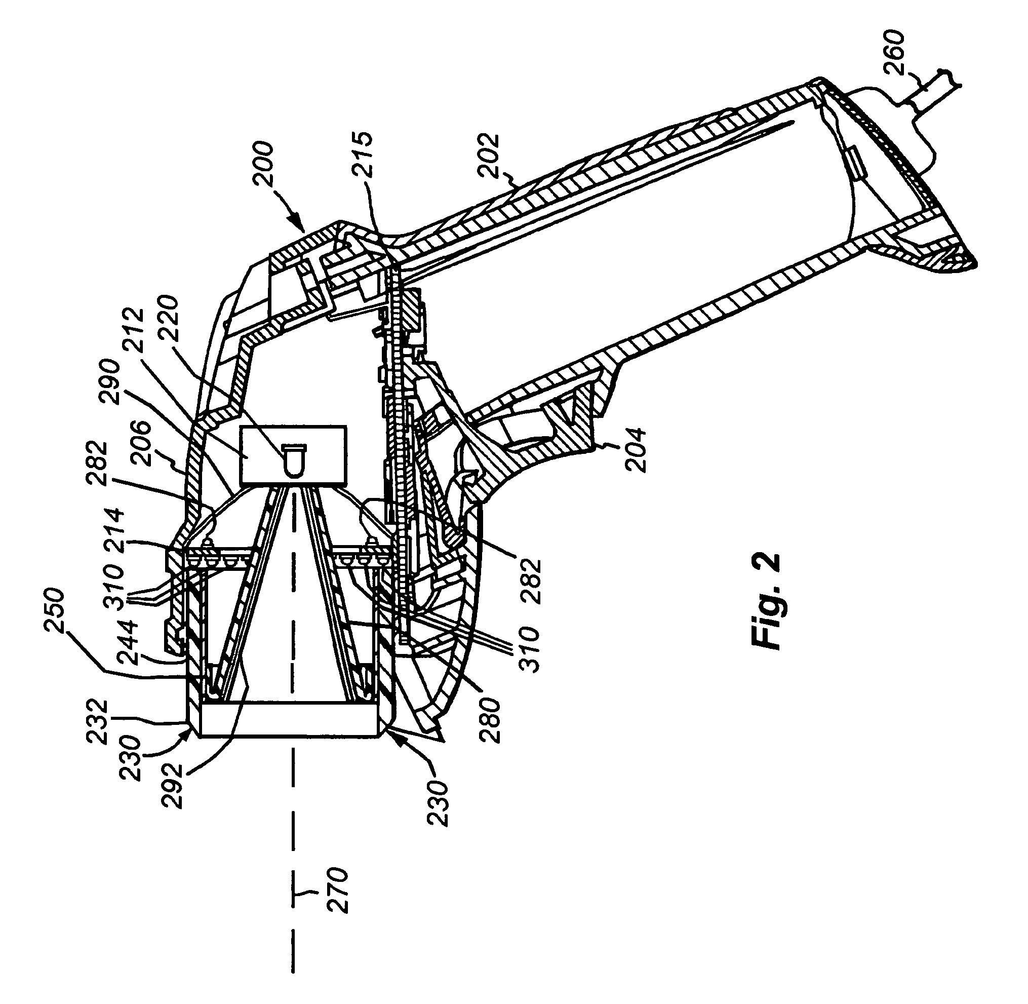
[0053]FIG. 2 shows a cross sectional side view of an illustrative embodiment of the reader 200 according to the present invention. The imager 212 and an illumination board 214 are positioned on a shock-resistant mounting (not shown) within the housing 206. In this exemplary embodiment, the processor module and related functional electronic components are mounted on a processor board 215. The grip portion 202 and the trigger 204 are functionally cooperative with the housing 206 and components of the processor board 215. The grip portion 206 includes a conveniently placed trigger 204 that can be actuated by a finger of the user to initiate the image acquisition and decoding function. More particularly, pressing the trigger causes all types and colors of illumination (as described further below) to be simultaneously projected onto the subject of interest, and also causes corresponding acquisition of an image by the imager.
[0054]With brief reference to the illuminator, the illumination ...
PUM
Abstract
Systems and methods provide an illumination assembly for a mark reader. A light transmitter is arranged in a surrounding relationship to an interior area, with the light transmitter having a proximal end and a distal end. An illumination source provides a light for transmission into the light transmitter. The light transmitter distal end allows the light from within the light transmitter to pass through and out of the distal end to provide bright field illumination and dark field illumination. The light transmitter distal end may include a first portion and a second portion, where light from within the light transmitter passes through and out of the first portion to provide bright field illumination, and light from within the light transmitter passes through and out of the second portion to provide dark field illumination.
Description
CROSS-REFERENCE TO RELATED APPLICATIONS[0001]This application is a continuation-in-part of U.S. patent application Ser. No. 13 / 294,286, filed Nov. 11, 2011 now U.S. Pat. No. 8,342,405, and entitled “Light Pipe Illumination System and Method,” which is a continuation of U.S. patent application Ser. No. 12 / 900,593 filed Oct. 8, 2010, now U.S. Pat. No. 8,061,614 dated Nov. 22, 2011, and entitled “Light Pipe Illumination System and Method,” which is a continuation of U.S. patent application Ser. No. 10 / 693,626 filed Oct. 24, 2003, now U.S. Pat. No. 7,823,783 dated Nov. 2, 2010, and also entitled “Light Pipe Illumination System and Method,” both of which are hereby incorporated by reference.[0002]This application is also a continuation-in-part of U.S. patent application Ser. No. 12 / 900,605 filed Oct. 8, 2010 now U.S. Pat. No. 8,672,227, and entitled “Low Profile Illumination for Direct Part Mark Reader,” which is a continuation of U.S. patent application Ser. No. 11 / 019,763 filed Dec. 21...
Claims
Application Information
Patent Timeline
Application Date:The date an application was filed.
Publication Date:The date a patent or application was officially published.
First Publication Date:The earliest publication date of a patent with the same application number.
Issue Date:Publication date of the patent grant document.
PCT Entry Date:The Entry date of PCT National Phase.
Estimated Expiry Date:The statutory expiry date of a patent right according to the Patent Law, and it is the longest term of protection that the patent right can achieve without the termination of the patent right due to other reasons(Term extension factor has been taken into account ).
Invalid Date:Actual expiry date is based on effective date or publication date of legal transaction data of invalid patent.

