Supercharge Your Innovation With Domain-Expert AI Agents!

Slat disconnect sensor

a sensor and wing technology, applied in the field of sensors, can solve problems such as loss of lift on the wing

Active Publication Date: 2020-03-03
HAMILTON SUNDSTRAND CORP
View PDF18 Cites 0 Cited by
  • Summary
  • Abstract
  • Description
  • Claims
  • Application Information

AI Technical Summary

Benefits of technology

This patent describes a sensor that detects when two objects move relative to each other. It includes two parts that move around an axis, and a fuse element that has two electrical contacts. When the parts are skewed, the contacts don't touch and the sensor produces an electrical signal. This information can be used to determine if the parts are in proper alignment.

Problems solved by technology

During an undesired condition, adjoining slats move relative to one another causing a loss of lift on the wing.

Method used


Image

  • Slat disconnect sensor
  • Slat disconnect sensor
  • Slat disconnect sensor

Examples


Embodiment Construction

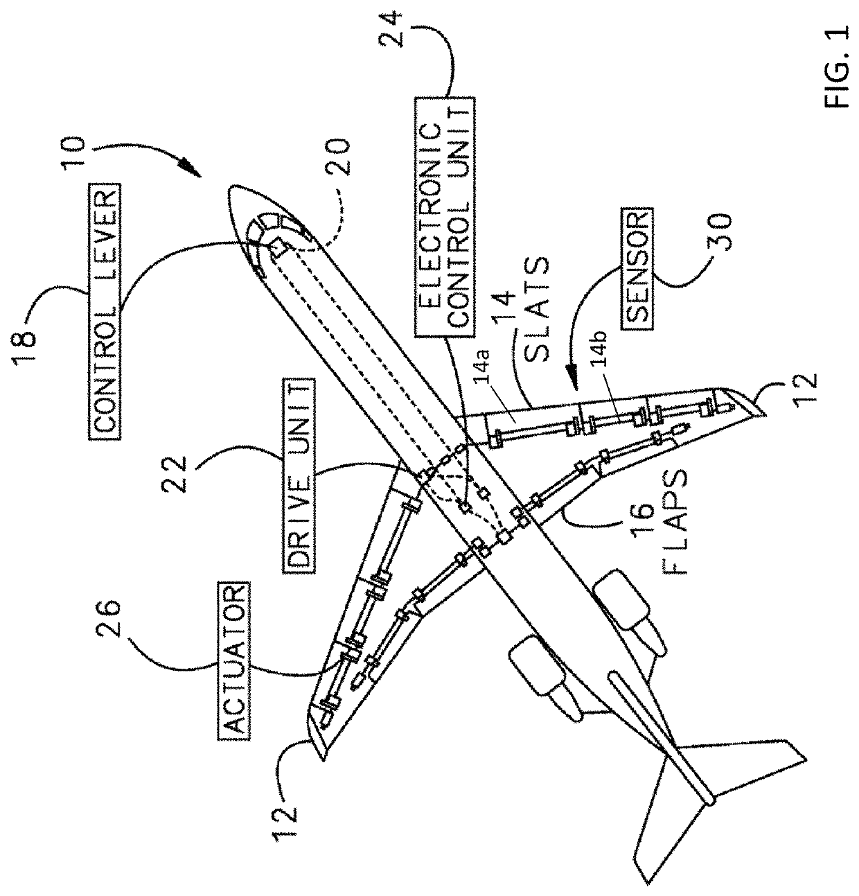
[0016]Referring now to FIG. 1, a typical aircraft 10 having two wings 12 is illustrated. Each wing 12 has a plurality of control surfaces, such as slats 14 and flaps 16 for example. These control surfaces are movable to control the lift of the aircraft 10. In an embodiment, a control lever 18 for operating at least one of the slats 14 and the flaps 16 is located in a cockpit and is operable by a pilot of the aircraft. A drive unit 22 controlled by an electronic control unit 24 transmits a torque to a plurality of actuators 26 which may be used to drive the slats 14 and / or flaps 16. A sensor 30 is attached between adjacent control surfaces to detect relative movement between the adjacent control surfaces.

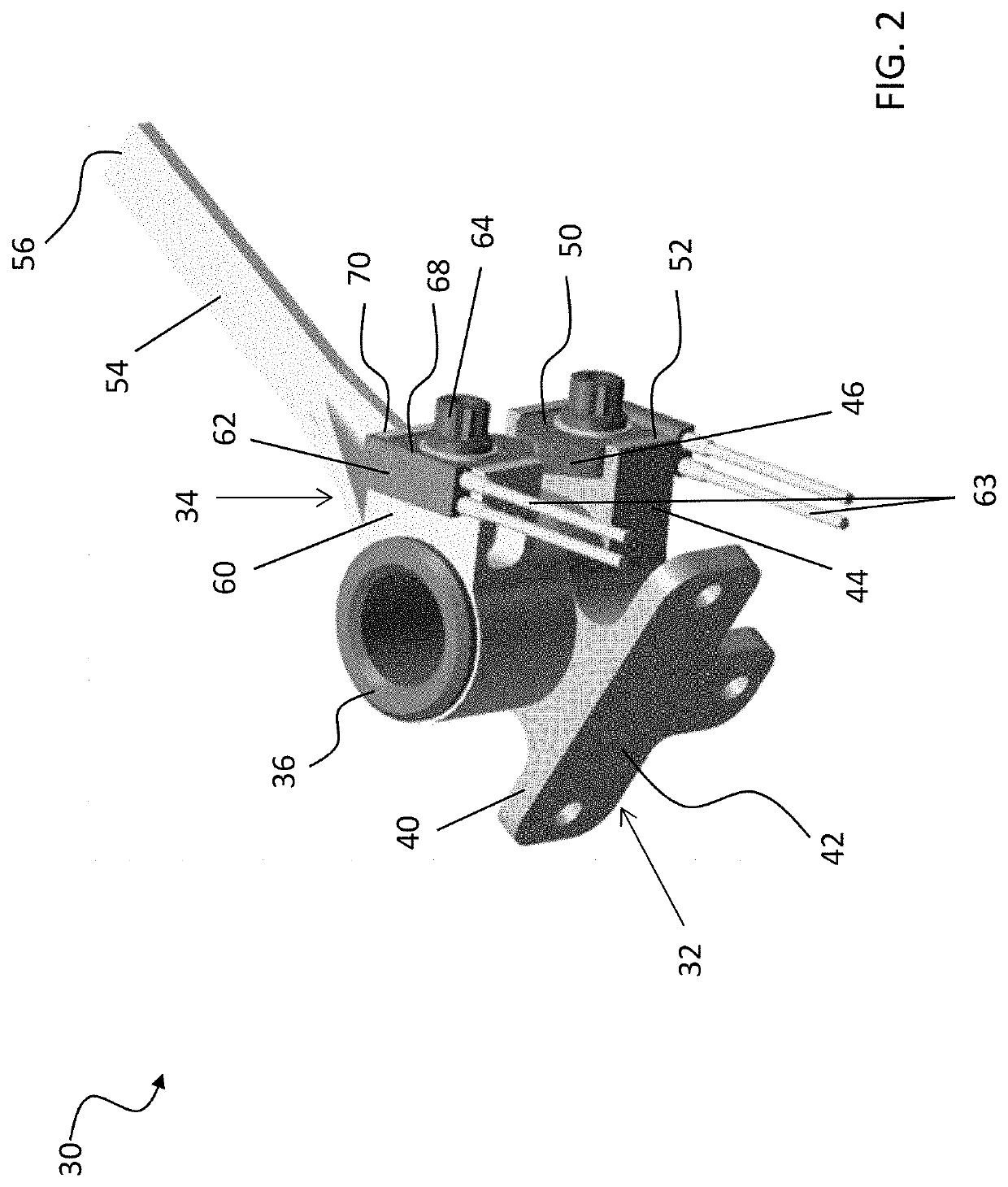
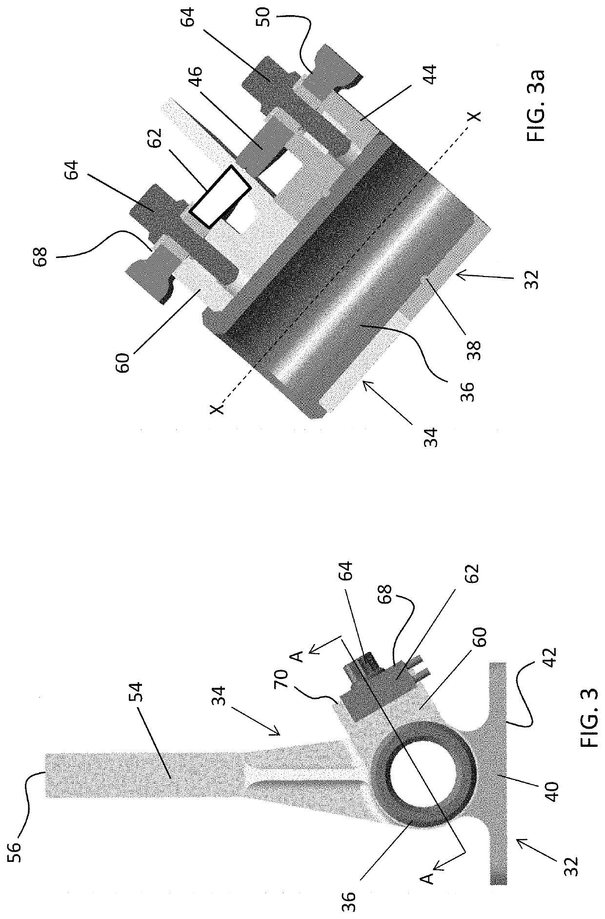
[0017]With reference now to FIGS. 2-7, an example of the sensor 30 is illustrated in more detail. The sensor 30 includes a first member 32 that may be associated with a first component, such as a first slat 14a for example, and a second member 34 that may be associated with a second,...


PUM


Abstract

A sensor for detecting relative movement between two adjacent components includes a first member, a second member rotatable about an axis relative to the first member, and a fuse element including a first electrical contactor connected to the first member and a second electrical contactor connected to the second member. When the first member and the second member are skewed, the first electrical contactor and the second electrical contactor are not in electrical contact.

Description

BACKGROUND OF THE INVENTION[0001]The subject matter disclosed herein relates to a sensor that detects skewed or disconnected adjacent movable components, and more particularly, to a sensor that detects skewed or disconnected aircraft control surface such as slats or flaps.[0002]Aircraft wings may employ lift changing devices that are often referred to as auxiliary airfoils or control surfaces. When extended, the surfaces increase the effective size, curvature, camber, and area of the wing thereby increasing the lift provided by the wing. During takeoff and landing of the aircraft, a pilot can extend these control surfaces from a leading or a trailing edge of a wing. Control surfaces that extend from the leading edge of the wing are referred to as slats, while control surfaces that extend from the trailing edge of the wing are referred to as flaps. Slats are used primarily to increase lift at large angles of attack (e.g., take off), while flaps are designed primarily to increase lift...

Claims


Application Information

Patent Timeline
Patent Type & Authority Patents(United States)
IPC IPC(8): G01B7/30B64D45/00G01D5/165
CPCG01B7/30B64D45/0005G01D5/165B64D2045/001
Inventor CARBONE, MICHAELBIELEFELDT, JOSEPH M.
Owner HAMILTON SUNDSTRAND CORP
Features
  • R&D
  • Intellectual Property
  • Life Sciences
  • Materials
  • Tech Scout
  • Unparalleled Data Quality
  • Higher Quality Content
  • 60% Fewer Hallucinations
Learn More