Pulse wave detection device and pulse wave detection program

a detection device and pulse wave technology, applied in image enhancement, angiography, television systems, etc., can solve problems such as making detection of pulses difficult, and achieve the effects of improving brightness correction, moving image brightness, and improving pulse wave detection accuracy

Active Publication Date: 2020-03-24
EQUOS RES
View PDF32 Cites 2 Cited by
  • Summary
  • Abstract
  • Description
  • Claims
  • Application Information

AI Technical Summary

Benefits of technology

[0027](1) According to the invention described in claim 1, brightness of a moving image can be corrected by obtaining a change in the brightness from an eye portion of a target.
[0028](2) According to the invention described in claim 2, the disturbance element shown on the moving image is excluded, only a skin portion is taken out, and a pulse wave can be detected therefrom and thus, accuracy of pulse wave detection can be improved.
[0029](3) According to the invention described in claim 3, the disturbance element shown on the moving image is excluded, only the eye portion is taken out, and accuracy of brightness correction can be improved.
[0030](4) According to the invention described in claim 4, the skin portion can be easily extracted from the moving image by comparison with a reference component.
[0031](5) According to the invention described in claim 5, robustness against the disturbance element can be improved by employing combination of color space components suitable for an observation target (since targets to be observed by light are different in a change in brightness, skin, and a pulse wave).
[0032](6) According to the invention described in claim 6, by combining a Y-component found to be suitable for detection of the change in brightness, an H-component found to be suitable for specification of the skin portion, and a Q-component found to be suitable for pulse wave detection, robustness against the disturbance element can be further improved.

Problems solved by technology

However, this technology is performed under an ideal environment of a laboratory, and there has been a problem that use in a practical scene such as detection of the pulse wave of a driver by mounting a pulse wave detection device on a vehicle, for example, there is a problem that a change in brightness becomes a disturbance element and makes detection of a pulse difficult.

Method used


Image

  • Pulse wave detection device and pulse wave detection program
  • Pulse wave detection device and pulse wave detection program
  • Pulse wave detection device and pulse wave detection program

Examples


first embodiment

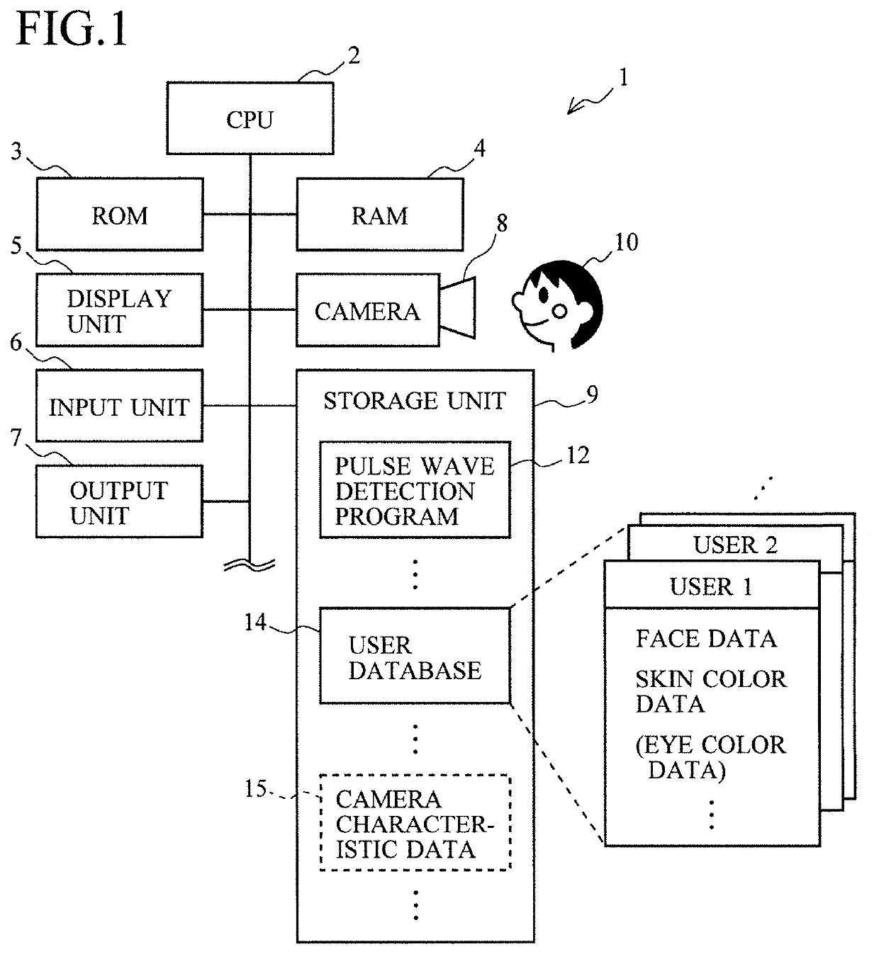
[0069]FIG. 1 is a view illustrating configuration of the pulse wave detection device 1 according to this embodiment.

[0070]The pulse wave detection device 1 is mounted on a vehicle, for example, and monitors a pulse wave of a passenger (a driver or a passenger on a seat next to the driver's) and grasps physiological states such as a physical condition or a tensed state of the driver.

[0071]Moreover, the device can be used for detecting / monitoring a pulse wave of a patient or a victim at a medical site or a disaster site.

[0072]The pulse wave detection device 1 includes a CPU (Central Processing Unit) 2, a ROM (Read Only Memory) 3, a RAM (Random Access Memory) 4, a display unit 5, an input unit 6, an output unit 7, a camera 8, a storage unit 9 and the like and detects (or estimates) the pulse wave of a user 10 (a target of pulse wave detection).

[0073]The CPU 2 is a central processing unit for executing various types of information processing or control in accordance with programs stored...

second embodiment

[0206]In the prior-art technology, pulse wave detection is made under the stable brightness by sunlight incident through the window of the laboratory.

[0207]On the other hand, when the pulse wave detection device 1 is to be used in a vehicle or at a medical site, photographing environments in use are varied, and particularly the brightness is expected to be changed during the pulse wave detection. Particularly when the pulse wave of a driver or a passenger is to be detected in the vehicle, a change in the brightness can frequently occur depending on a change in a running position or direction of the vehicle and a time slot.

[0208]Thus, whether or not a detection result is influenced by a brightness change caused when the pulse wave detection device 1 is actually used was examined. That is, the inventor of the present application changed the brightness by casting a shadow on the face of the subject using a round fan while the pulse wave was being detected under illumination by a fluore...

third embodiment

[0276]When the general-purpose camera 8 is used, for example, it is not known in a case where a human being appreciates a moving image, but there is fluctuation in characteristics in each pixel to such a degree that obstructs detection of the pulse wave.

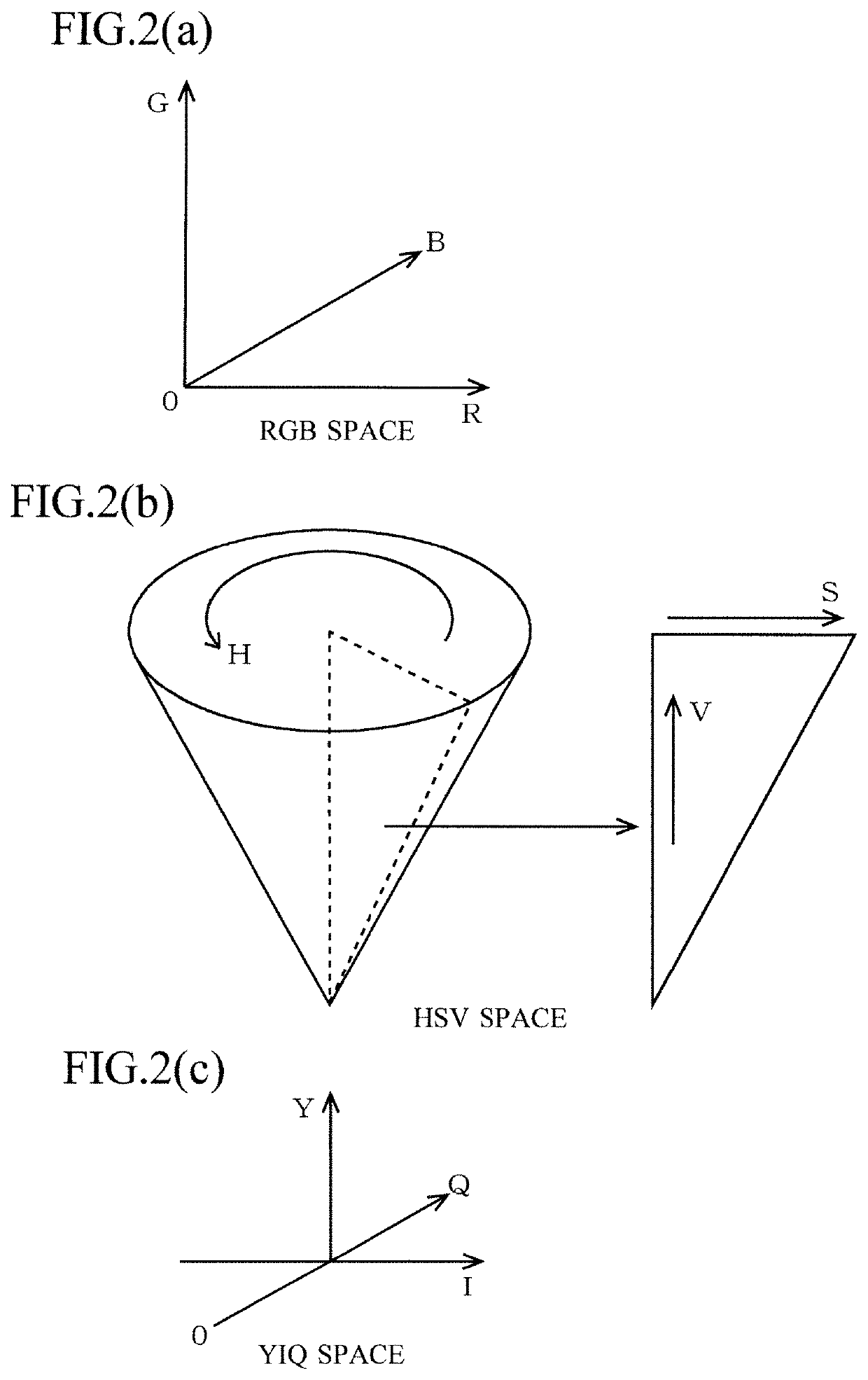
[0277]In this embodiment, since the pulse wave is detected by the color component, it is affected by the fluctuation in chrominance (color quality) characteristics.

[0278]FIG. 12 are a view for explaining the fluctuation in chrominance by the camera characteristics.

[0279]FIG. 12(a) is a view illustrating the fluctuation in the chrominance characteristics of the pixel in the camera 8 by contrast.

[0280]Since the chrominance characteristics are not uniform as above, if the user moves in the screen, a value of the chrominance is changed, which affects accuracy of pulse wave detection.

[0281]FIG. 12(b) is a view illustrating comparison of the detected pulse waves in a left region 61, a center region 62, and a right region 63 in the screen b...


PUM


Abstract

A pulse wave detection device color converts a frame image of a moving image from RBG components to YIQ components, and identifies an eye section using the eye color of a user prepared in advance with a Q component. Next, the pulse wave detection device uses the Y values of the eye section to detect the brightness of the imaging environment. Then, the pulse wave detection device detects a pulse wave signal Qm on the basis of the average of the Q-values of a skin section in the frame image, corrects a change in the brightness by subtracting from Qm the average value Ye of the Y values of the eye section, and thereby outputs a post-brightness-correction Qm. As a result, a pulse wave can be successfully detected even if the brightness is changing because the user is moving in a vehicle or the like.

Description

TECHNICAL FIELD[0001]The present invention relates to a pulse wave detection device and a pulse wave detection program and relates to those detecting a pulse wave by using image processing, for example.BACKGROUND ART[0002]Detection of a pulse wave is extremely important in understanding a physiological state of a human being and a technology for detecting this from a remote place in a non-contact manner is in demand.[0003]Such technologies include a study made by Massachusetts Institute of Technology which is a non-patent literature.[0004]This technology detects a pulse wave by taking a moving image of the face of a subject by a web camera and analyzing the moving image by a laptop computer after the photographing (that is, not by real-time processing but by processing later).[0005]This study realizes non-contact detection of a pulse wave by using an inexpensive general purpose device and a simple method against conventional detection of the pulse wave by using a special expensive d...

Claims


Application Information

Patent Timeline
Patent Type & Authority Patents(United States)
IPC IPC(8): A61B5/021H04N5/232G06T7/20G06T7/90G06T1/00H04N5/57
CPCH04N5/57G06T7/90H04N5/23216A61B5/02108G06T7/20G06T1/0007G06T2207/30041G06T2207/30201A61B5/0261A61B5/0077A61B3/1241A61B2576/02A61B5/0245A61B5/00H04N23/62
Inventor JONES, MICHAELYAMADA, HIDEO
Owner EQUOS RES
Why Eureka
Try Eureka