
Image processing apparatus and image processing method thereof

a technology of image processing and control methods, applied in the field of image processing apparatuses and control methods thereof, can solve the problems of loss of subject details, drop in the s/n ratio of the corrected area, etc., and achieve the effect of suppressing noise amplification and loss of subject details

Active Publication Date: 2017-01-19
CANON KK
View PDF16 Cites 11 Cited by
  • Summary
  • Abstract
  • Description
  • Claims
  • Application Information

AI Technical Summary

Benefits of technology

The present invention is an image processing apparatus and control method that can brighten or adjust the brightness of pixels without amplifying noise or losing important details. This solves issues that were present with conventional techniques.

Problems solved by technology

However, increasing the gain amplifies noise components in addition to signal components, which causes a drop in the S / N ratio of the corrected area.
Japanese Patent Laid-Open No. 2010-135996 does apply a noise reduction filter in order to suppress a drop in the S / N ratio, but the noise reduction process is the application of smoothing, which can cause a loss of details in the image.

Method used


Image

  • Image processing apparatus and image processing method thereof
  • Image processing apparatus and image processing method thereof
  • Image processing apparatus and image processing method thereof

Examples


first embodiment

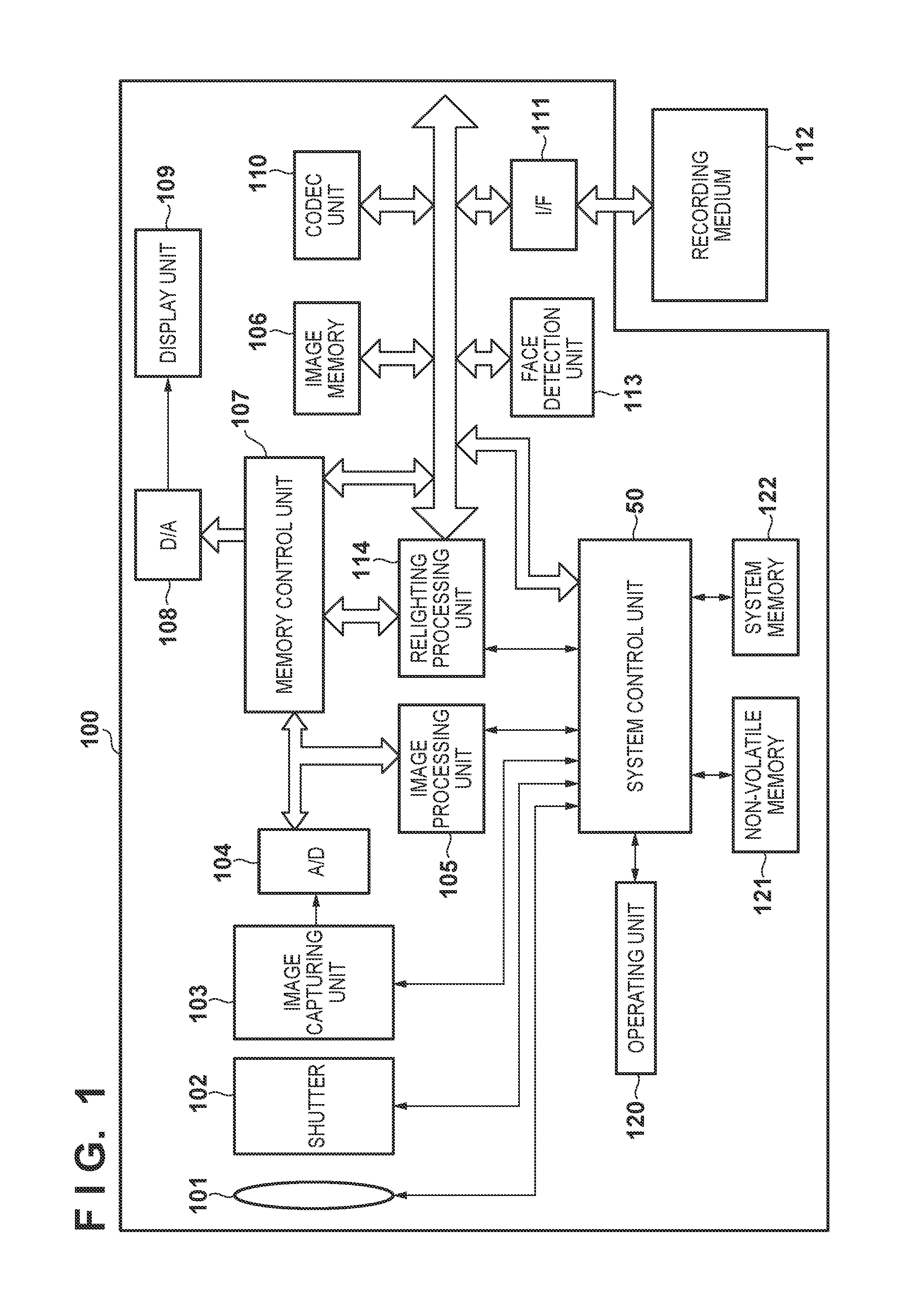
[0024]FIG. 1 is a block diagram illustrating an example of the configuration of a digital camera 100 according to a first embodiment of the present invention.

[0025]In FIG. 1, a lens group 101 corresponds to a zoom lens including a focus lens. A shutter 102 having an aperture function is provided between the lens group 101 and an image capturing unit 103. The image capturing unit 103 has an image sensor such as a CCD / CMOS image sensor, which converts an optical image formed by the lens group 101 on an image plane into electrical signals on a pixel-by-pixel basis. An A / D converter 104 converts an analog signal output by the image capturing unit 103 into a digital signal (image data).

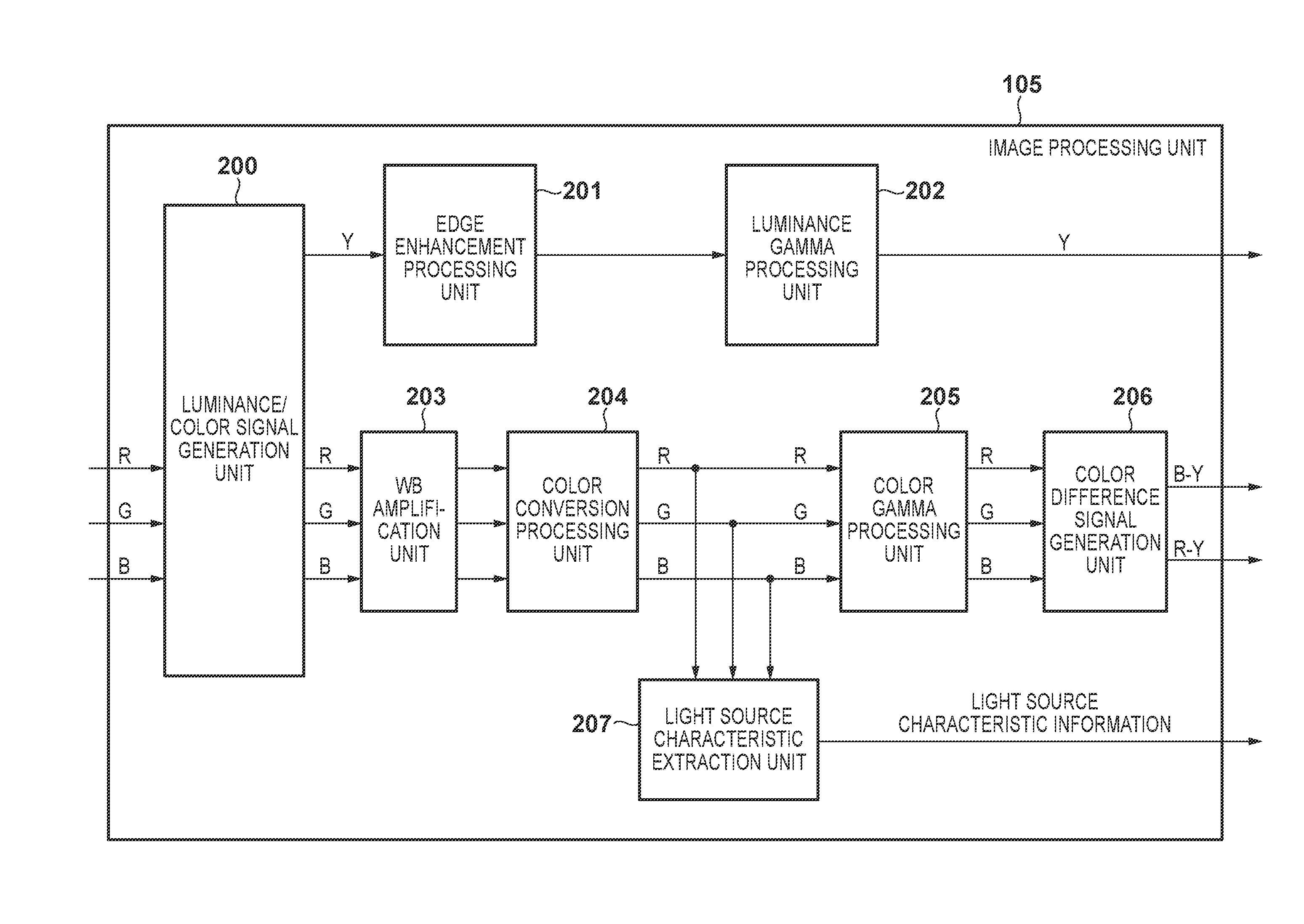
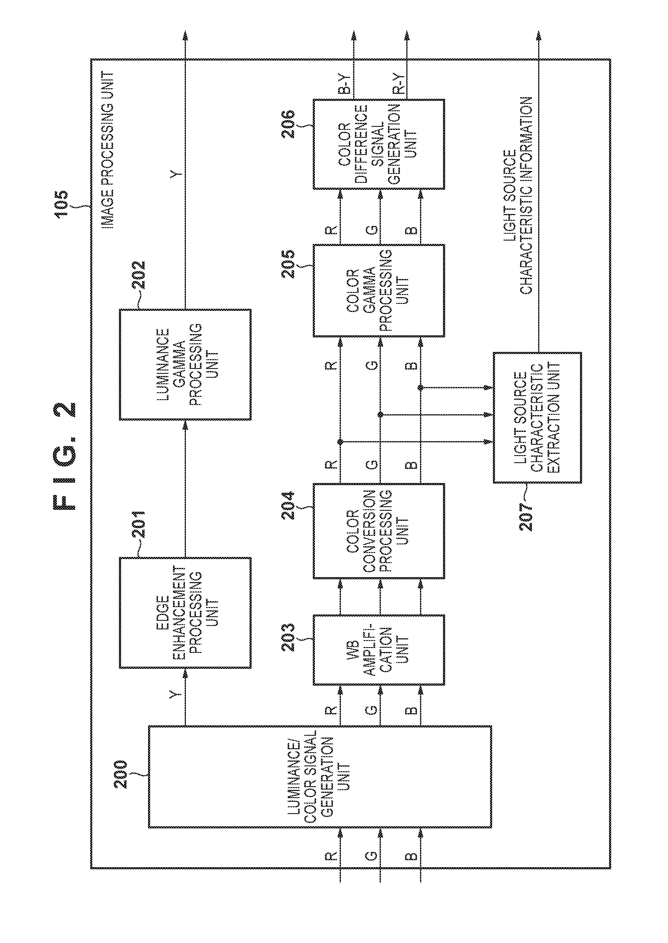
[0026]An image processing unit 105 carries out various types of image processing on the image data output from the A / D converter 104, such as color interpolation (demosaicing), white balance adjustment, γ correction, edge enhancement, noise reduction, color correction, and the like. An image memory 106 tem...

second embodiment

[0101]Next, a second embodiment of the present invention will be described. While the first embodiment describes estimating the virtual light reflection color from a single captured image, the second embodiment describes estimation using a plurality of captured images. As such, only the internal configuration of the relighting processing unit 114 and operations performed by the system control unit 50, which are different from those in the first embodiment, will be described hereinafter.

[0102]FIG. 8A is a flowchart illustrating operations performed by the system control unit 50 when capturing an image, according to the present embodiment. In S801 of FIG. 8A, the system control unit 50 determines a capturing mode. It is assumed that the user can switch the capturing mode between a capturing mode that applies relighting and a normal capturing mode by operating the operating unit 120. The system control unit 50 advances the processing to S802 in the case where the capturing mode that ap...


PUM


Abstract

Disclosed is an image processing apparatus and a control method thereof that can correct the brightness of a pixel in an image. Reflection characteristics of environment light when the image is captured are estimated by applying smoothing to the image. The brightness of the pixel is corrected by computing a correction value for correcting the brightness of the pixel based on the reflection characteristics of the environment light and adding the correction value to the pixel. The brightness can be corrected while suppressing an amplification of noise and a loss of details of a subject.

Description

TECHNICAL FIELD[0001]The present invention relates to image processing apparatuses and control methods thereof, and particularly relates to techniques for correcting the brightness of an image.BACKGROUND ART[0002]A conventional technique for correcting brightness (“relighting”) by illuminating a subject in an image with light from a virtual light source is known (Japanese Patent Laid-Open No. 2010-135996). This technique makes it possible to brighten dark areas such as shadows produced by environment light, which enables the image to be corrected so that a subject present in blocked-up shadows, for example, can be recognized.[0003]In the case of relighting on a facial area, for example, an area having a lower luminance than an average luminance of the overall facial area is extracted as a shadow area and the brightness of the shadow area is increased, and as a result shadows in a facial area can be suppressed without affecting the brightness of other areas.[0004]The method disclosed...

Claims


Application Information

Patent Timeline
Patent Type & Authority Applications(United States)
IPC IPC(8): H04N9/77H04N9/73G06T5/00H04N23/76H04N23/12
CPCH04N9/77G06T2207/10024H04N9/735G06T5/002G03B7/08G03B7/28H04N23/12H04N23/88G06T5/94G06T5/70
Inventor KITAJIMA, KOTARO
Owner CANON KK
Learn More