Height-adjustable stand for a flat-screen television

a technology for flat-screen televisions and stands, applied in the field of stands, can solve the problems of inconvenient, laborious and inconvenient, and the user can only swivel the tv to either side, and achieve the effect of easy raising or lowering the tv and easy adjustment of the height of the attached tv

Active Publication Date: 2020-04-14
COPELAND TODD W
View PDF10 Cites 0 Cited by
  • Summary
  • Abstract
  • Description
  • Claims
  • Application Information

AI Technical Summary

Benefits of technology

[0005]The present invention relates to a television stand comprising an elongated, vertical support pole having a front surface, a rear surface, a curved top portion, a bottom end and a hollow interior. Within the hollow interior is a motorized drive belt having a carriage attached thereto that is adapted to fasten to an existing television stand or directly to the rear surface of most existing televisions. Accordingly, using a local control panel, a remote unit or a portable electronic device, a viewer can easily raise or lower the television to a desired height. Also, as the television moves along the curved top portion of the pole, the curvature tilts the television downwardly, toward the viewer.
[0006]It is therefore an object of the present invention to provide a stand that allows a user to easily adjust the height of an attached television.

Problems solved by technology

However, because the height of the support surface is fixed, the user can only swivel the TV to either side.
Though some entertainment centers are equipped with adjustable platforms, they only allow the TV to be laterally rotated or perhaps vertically tilted within a limited range.
And even though the screen angle may be acceptable, the television is often fixed at an undesirable height.
The user must then raise or lower the support surface, if possible, which is laborious and inconvenient.
Otherwise, the viewer must tolerate an unacceptable viewing position.

Method used


Image

  • Height-adjustable stand for a flat-screen television
  • Height-adjustable stand for a flat-screen television

Examples


Embodiment Construction

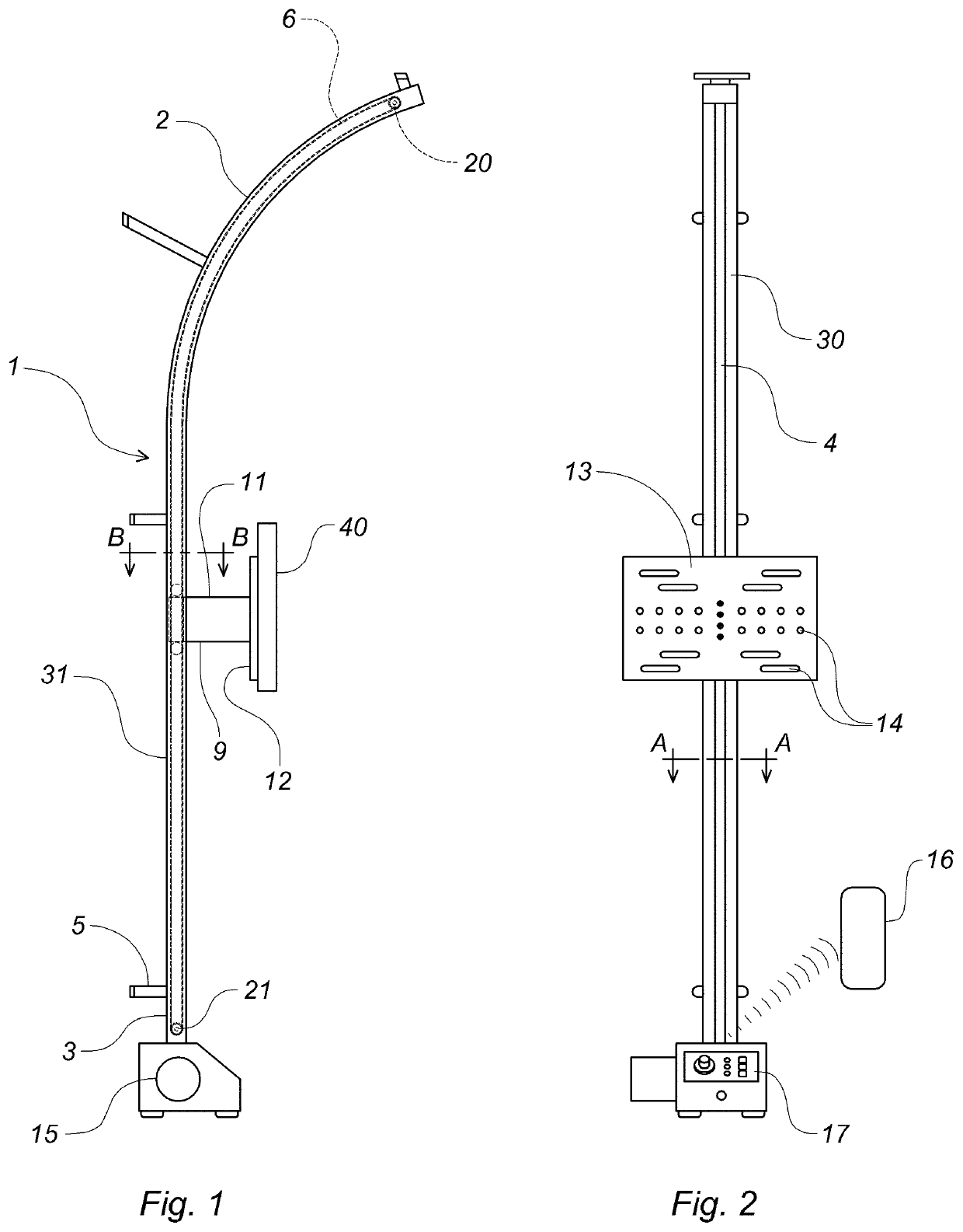
[0015]The present invention relates to a television stand comprising an elongated, vertical support pole 1 having a substantially C-shaped cross-sectional configuration. The support pole includes front surface 30, a rear surface 31, a curved top portion 2, a bottom end 3 and a hollow interior. A longitudinal slot 4 extending along the entire front surface is in communication with the hollow interior. On the rear surface are multiple brackets 5 with associated fasteners for anchoring the pole to wall studs.

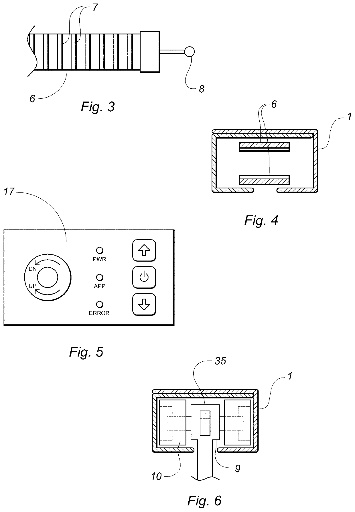
[0016]Within the hollow interior is a drive belt 6 having a ribbed inner surface 7 that engages an idler sprocket 20 at the top end of the pole and a motorized sprocket 21 at the bottom end. Each end of the belt includes an eyelet 8 for fastening to a ring 35 on either the upper or lower side of a carriage block 9, described, infra.

[0017]The carriage block 9 includes a pair of opposing wheels 10 that ride on two opposing interior surfaces of the pole. Horizontally extending from th...


PUM


Abstract

A television stand includes an elongated, vertical support pole having a front surface, a rear surface, a curved top portion, a bottom end and a hollow interior. Within the hollow interior is a motorized drive belt that moves an external carriage that is adapted to fasten to an existing television or television stand. Accordingly, using a local control panel, a remote unit or a portable electronic device, a viewer can easily raise or lower the television to a desired height. Also, when the television is raised to the upper portion of the pole, the curvature tilts the television downwardly, toward the viewer.

Description

CROSS REFERENCE TO RELATED APPLICATIONS[0001]This application is entitled to the benefit of provisional patent application No. 62 / 401,417 filed on Sep. 29, 2016, the specification of which is incorporated herein by reference.BACKGROUND OF THE INVENTION[0002]The present invention relates to a unique stand that allows a user to easily adjust the height and angle of a large-screen television.DESCRIPTION OF THE PRIOR ART[0003]A larger or “flat-screen” television is typically supported on a stand that is placed on a table, entertainment center or other support surface. However, because the height of the support surface is fixed, the user can only swivel the TV to either side. Though some entertainment centers are equipped with adjustable platforms, they only allow the TV to be laterally rotated or perhaps vertically tilted within a limited range. And even though the screen angle may be acceptable, the television is often fixed at an undesirable height. The user must then raise or lower t...

Claims


Application Information

Patent Timeline
Patent Type & Authority Patents(United States)
IPC IPC(8): F16M11/00F16M11/10F16M11/18F16M11/04
CPCF16M11/10F16M11/048F16M11/046F16M11/18F16M11/425
Inventor COPELAND, TODD W
Owner COPELAND TODD W
Why Eureka
Try Eureka