Production method for electrochemically stable anode particulates for lithium secondary batteries

a production method and anode particulate technology, applied in secondary cell servicing/maintenance, cell components, sustainable manufacturing/processing, etc., can solve the problems of dramatically increasing the charge/discharge cycle number and reducing the battery capacity decay ra

Active Publication Date: 2020-04-21
GLOBAL GRAPHENE GRP INC
View PDF150 Cites 18 Cited by
  • Summary
  • Abstract
  • Description
  • Claims
  • Application Information

AI Technical Summary

Benefits of technology

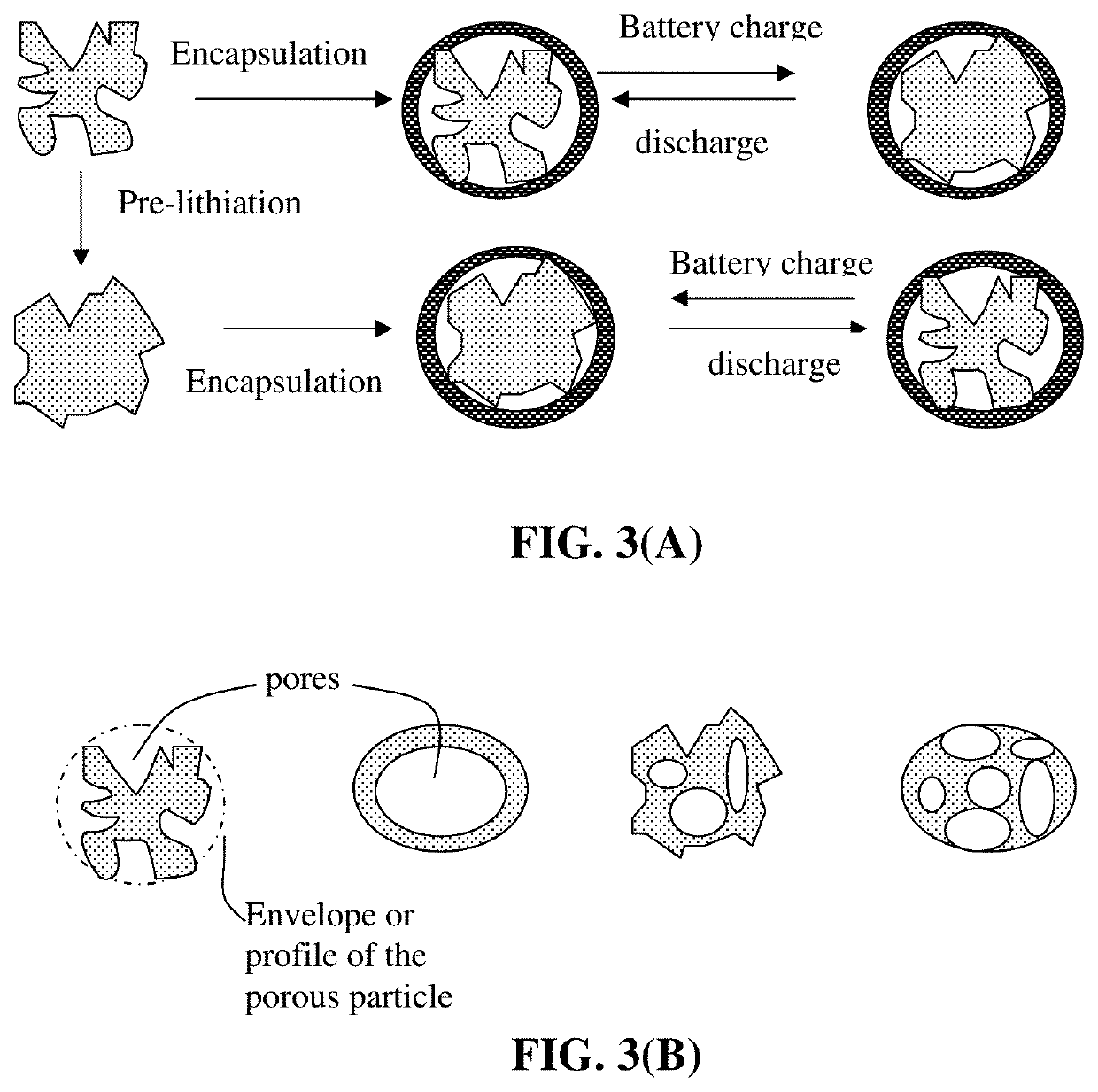
[0017]This amount of pore volume provides empty space to accommodate the volume expansion of the anode active material so that the thin encapsulating layer would not significantly expand (not to exceed 50% volume expansion of the particulate) when the lithium battery is charged. Preferably, the particulate does not increase its volume by more than 20%, further preferably less than 10% and most preferably by approximately 0% when the lithium battery is charged. Such a constrained volume expansion of the particulate would not only reduce or eliminate the volume expansion of the anode electrode but also reduce or eliminate the issue of repeated formation and destruction of a solid-electrolyte interface (SEI) phase. We have discovered that this strategy surprisingly results in significantly reduced battery capacity decay rate and dramatically increased charge / discharge cycle numbers. These results are unexpected and highly significant with great utility value.
[0030]When graphene is used in the particulate, the graphene sheets preferably have a lateral dimension (length or width) from 5 nm to 5 μm, more preferably from 10 nm to 1 μm, and most preferably from 10 nm to 300 nm. Shorter graphene sheets allow for easier encapsulation and enable faster lithium ion transport through the encapsulating layer.
[0050]The method may further comprise a procedure of operating the lithium battery in such a manner that the anode is at an electrochemical potential below 1.5 V vs. Li / Li+ during at least one of the first 10 charge / discharge cycles of the battery, typically during the first 3 cycles, after the lithium battery is made. This procedure enables the particulate surfaces to become electrochemically stable.

Problems solved by technology

We have discovered that this strategy surprisingly results in significantly reduced battery capacity decay rate and dramatically increased charge / discharge cycle numbers.

Method used


Image

  • Production method for electrochemically stable anode particulates for lithium secondary batteries
  • Production method for electrochemically stable anode particulates for lithium secondary batteries
  • Production method for electrochemically stable anode particulates for lithium secondary batteries

Examples


example 1

Oxide from Sulfuric Acid Intercalation and Exfoliation of MCMBs and Production of Graphene / Carbon-Encapsulated Particles

[0159]MCMB (mesocarbon microbeads) were supplied by China Steel Chemical Co. This material has a density of about 2.24 g / cm3 with a median particle size of about 16 μm. MCMBs (10 grams) were intercalated with an acid solution (sulfuric acid, nitric acid, and potassium permanganate at a ratio of 4:1:0.05) for 48 hours. Upon completion of the reaction, the mixture was poured into deionized water and filtered. The intercalated MCMBs were repeatedly washed in a 5% solution of HCl to remove most of the sulfate ions. The sample was then washed repeatedly with deionized water until the pH of the filtrate was neutral. The slurry was dried and stored in a vacuum oven at 60° C. for 24 hours. The dried powder sample was placed in a quartz tube and inserted into a horizontal tube furnace preset at a desired temperature, 800° C.-1,100° C. for 30-90 seconds to obtain graphene sa...

example 2

and Exfoliation of Natural Graphite

[0161]Graphite oxide was prepared by oxidation of graphite flakes with sulfuric acid, sodium nitrate, and potassium permanganate at a ratio of 4:1:0.05 at 30° C. for 48 hours, according to the method of Hummers [U.S. Pat. No. 2,798,878, Jul. 9, 1957]. Upon completion of the reaction, the mixture was poured into deionized water and filtered. The sample was then washed with 5% HCl solution to remove most of the sulfate ions and residual salt and then repeatedly rinsed with deionized water until the pH of the filtrate was approximately 4. The intent was to remove all sulfuric and nitric acid residue out of graphite interstices. The slurry was dried and stored in a vacuum oven at 60° C. for 24 hours.

[0162]The dried, intercalated (oxidized) compound was exfoliated by placing the sample in a quartz tube that was inserted into a horizontal tube furnace preset at 1,050° C. to obtain highly exfoliated graphite. The exfoliated graphite was dispersed in water...

example 3

on of Pristine Graphene Sheets

[0164]Pristine graphene sheets were produced by using the direct ultrasonication or liquid-phase exfoliation process. In a typical procedure, five grams of graphite flakes, ground to approximately 20 μm in sizes, were dispersed in 1,000 mL of deionized water (containing 0.1% by weight of a dispersing agent, Zonyl® FSO from DuPont) to obtain a suspension. An ultrasonic energy level of 85 W (Branson S450 Ultrasonicator) was used for exfoliation, separation, and size reduction of graphene sheets for a period of 15 minutes to 2 hours. The resulting graphene sheets were pristine graphene that had never been oxidized and were oxygen-free and relatively defect-free. There are substantially no other non-carbon elements. These graphene sheets were used as a conducting material in the core or as a shell carbonaceous / graphitic material.


PUM

PropertyMeasurementUnit
lithium ion conductivityaaaaaaaaaa
thicknessaaaaaaaaaa

Abstract

Provided is a method of producing multiple anode particulates, comprising: a) dispersing an electrically conducting material, primary particles of an anode active material, an optional electron-conducting material, and a sacrificial material in a liquid medium to form a precursor mixture; b) forming the precursor mixture into droplets and drying the droplets; and c) removing the sacrificial material or thermally converting the sacrificial material into a carbon material to obtain multiple particulates, wherein a particulate comprises one or a plurality of anode active material particles having a volume Va, an electron-conducting material, and pores having a volume Vp which are encapsulated by a thin encapsulating layer having a thickness from 1 nm to 10 μm and a lithium ion conductivity from 10−8 S / cm to 5×10⁻² S / cm and the volume ratio Vp / Va in the particulate is from 0.3 / 1.0 to 5.0 / 1.0.

Description

[0001]The present invention relates generally to the field of rechargeable lithium battery and, more particularly, to the anode active materials in the form of particulates secondary particles containing a core of anode active material primary particles and pores encapsulated by a thin shell (a thin encapsulating layer) containing a carbonaceous or graphitic material and a method of producing same.BACKGROUND OF THE INVENTION[0002]A unit cell or building block of a lithium-ion battery is typically composed of an anode current collector, an anode or negative electrode layer (containing an anode active material responsible for storing lithium therein, a conductive additive, and a resin binder), an electrolyte and porous separator, a cathode or positive electrode layer (containing a cathode active material responsible for storing lithium therein, a conductive additive, and a resin binder), and a separate cathode current collector. The electrolyte is in ionic contact with both the anode ...

Claims


Application Information

Patent Timeline
Patent Type & Authority Patents(United States)
IPC IPC(8): H01M10/44H01M4/36H01M10/0525H01M10/058H01M4/587H01M4/38H01M4/02H01M4/52H01M4/48
CPCH01M10/058H01M10/0525H01M4/587H01M4/366H01M4/523H01M4/387H01M4/386H01M2004/027H01M4/483H01M4/38H01M4/382H01M4/405H01M4/62H01M4/622H01M4/623H01M4/624H01M4/625H01M4/626H01M10/049H01M10/446H01M4/0447Y02E60/10Y02P70/50
Inventor JANG, BOR Z.
Owner GLOBAL GRAPHENE GRP INC
Why Eureka
Try Eureka