Valve for inflation/deflation

a valve and inflation technology, applied in the field of valves for inflation/deflation, to achieve the effect of preventing air from escaping

Active Publication Date: 2020-05-05
ARGON TECH INC
View PDF19 Cites 1 Cited by
  • Summary
  • Abstract
  • Description
  • Claims
  • Application Information

AI Technical Summary

Benefits of technology

[0008]This disclosure, in at least on aspect, relates to a valve system and more particularly, air valves for inflating and / or deflating an inflatable device, such as an air pad. The valve may include a housing that holds a valve. The housing may be integrated into the lining of the inflatable device and is secured to the inflatable device. “Integrated” for purposes of this disclosure means part of the inflatable device itself, non-removable and not separate from, or unitary. The valve is secured to the housing and it may be permanently secured or reversibly secured. The housing may also include a cap coupled to the housing which may provide an added feature for preventing the escape of air.
[0009]The valve may sit entirely or partially within the housing and may be rotatable about an axis. A valve rotation feature may allow the valve to freely rotate within the housing to allow air into the inflatable device or out of the inflatable device. A stop may be positioned within the housing to allow the valve to only rotate 180 degrees from an “inflation position” to a “deflation position” or vice versa. The valve may sit securely within the housing preventing any air from entering or escaping around the outer edge of the valve which engages an inner ring of the housing.
[0010]The valve may include a rigid center portion that engages an umbrella valve, or rubber flap, that lays flat against the center portion of the valve that allows one-way passage of air because the air pressure pushes the flap against the opening with the center portion preventing escape of air. The valve is configured in a way to allow for ease of inflation and deflation without unnecessary pressure, force, twisting, squeezing, or the like.

Problems solved by technology

Furthermore, the valve contemplated herein provides a user with the unwanted air “escape” while attempting to inflate an inflatable device.

Method used


Image

  • Valve for inflation/deflation
  • Valve for inflation/deflation
  • Valve for inflation/deflation

Examples


Embodiment Construction

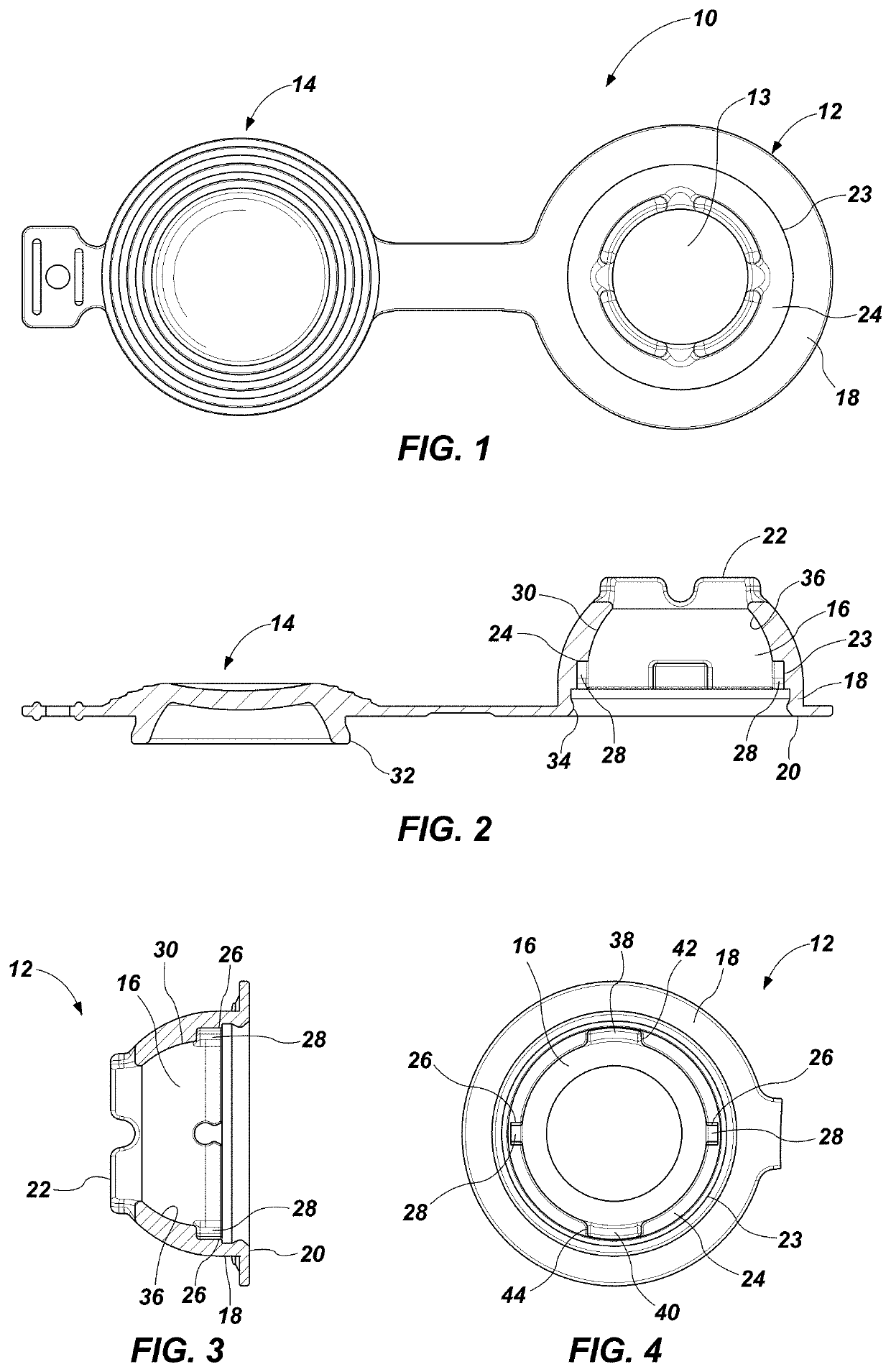
[0030]The following description sets forth separate embodiments of a valve system for use in an inflatable device. The valve system may be utilized to inflate, deflate, or both, the inflatable device by allowing one-way passage of air (or other medium, such as water, used to inflate a device). In addition, the valve system described herein may allow for mass deflation by bypassing the one-way valve. A valve, when in a first configuration, may allow for passage of air into the inflatable device while preventing air from reversing through the valve out of the inflatable device. The valve, when in a second configuration, may allow for passage of air out of the inflatable device while preventing air from reversing through the valve in to the inflatable device.

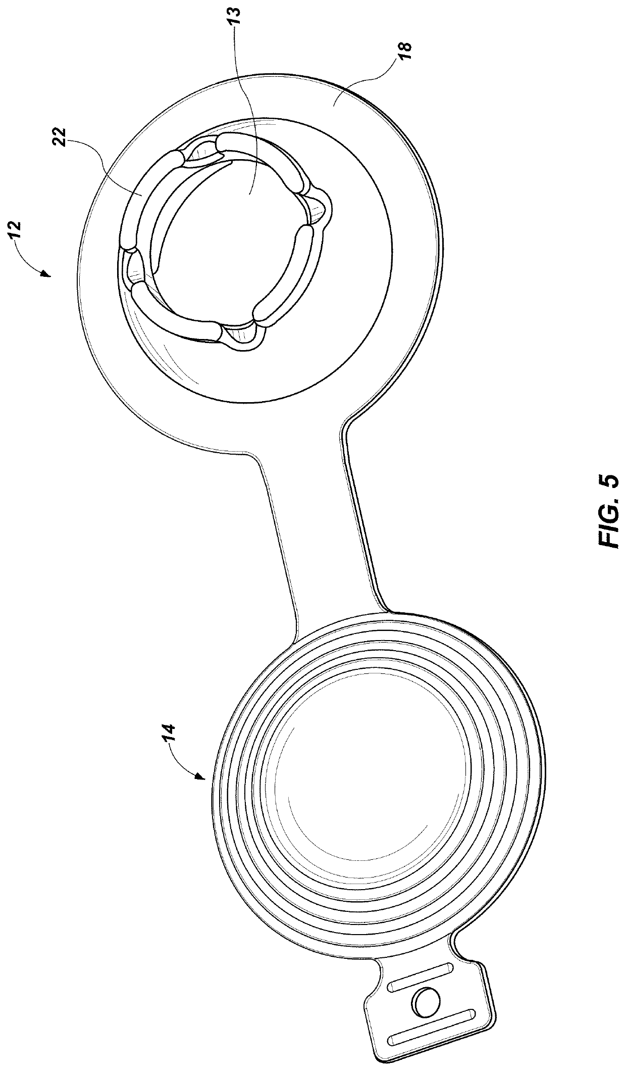
[0031]FIGS. 1 and 2 illustrate a valve system 10, with a housing 12, a cap 14 coupled to the housing 12 and a valve 16 positioned at least partially within the housing 12. The housing 12 may be integrated into or secured to an infl...


PUM


Abstract

Apparatus and method of a valve assembly that may be integrated into an inflatable device. The valve assembly may include a valve that is rotatable within a housing. The valve may allow for one-way passage of air either into or out of the inflatable device depending on the configuration of the valve. The valve system may provide an easy way to both inflate and deflate an inflation device with minimal effort from a user.

Description

CROSS-REFERENCE TO RELATED APPLICATIONS[0001]This application claims priority to U.S. Provisional Patent Application No. 62 / 354,221 entitled VALVE FOR INFLATION / DEFLATION filed Jun. 24, 2016, which is incorporated herein by reference in its entirety.TECHNICAL FIELD[0002]This disclosure relates generally to a valve on, or integrated with, inflatable devices such as air mattresses and pads and, more specifically, a valve that can be used both to inflate and deflate an inflatable device. The valve may be rotatable such that air may flow in only a single direction and depending on the configuration of the valve may allow for inflation or deflation of an inflatable apparatus.RELATED ART[0003]As will be appreciated by any person who has ever used an inflatable device that most often the valves easily allow one-way flow of air either into or out of the inflatable device. It is also common to have an umbrella valve that will allow one way passage of air. It is also typical to have a push or...

Claims


Application Information

Patent Timeline
Patent Type & Authority Patents(United States)
IPC IPC(8): F16K15/03F16K15/18F16K31/524F16K15/20
CPCF16K31/52441F16K15/18F16K15/20F16K31/52425Y10T137/5153Y10T137/36
Inventor MAXFIELD, MATTHEWTHOLL, CORY
Owner ARGON TECH INC
Why Eureka
Try Eureka