Agricultural baler with flywheel brake control
a technology of flywheel and brake control, which is applied in the field of agricultural balers, can solve the problems of not being able to provide the high torque needed to bring the flywheel up to its steady speed, the solution is not entirely satisfactory, and the tractor engine may stall, etc., and achieves good start-up behavior. , good start-up
- Summary
- Abstract
- Description
- Claims
- Application Information
AI Technical Summary
Benefits of technology
Problems solved by technology
Method used
Image


Examples
example 1
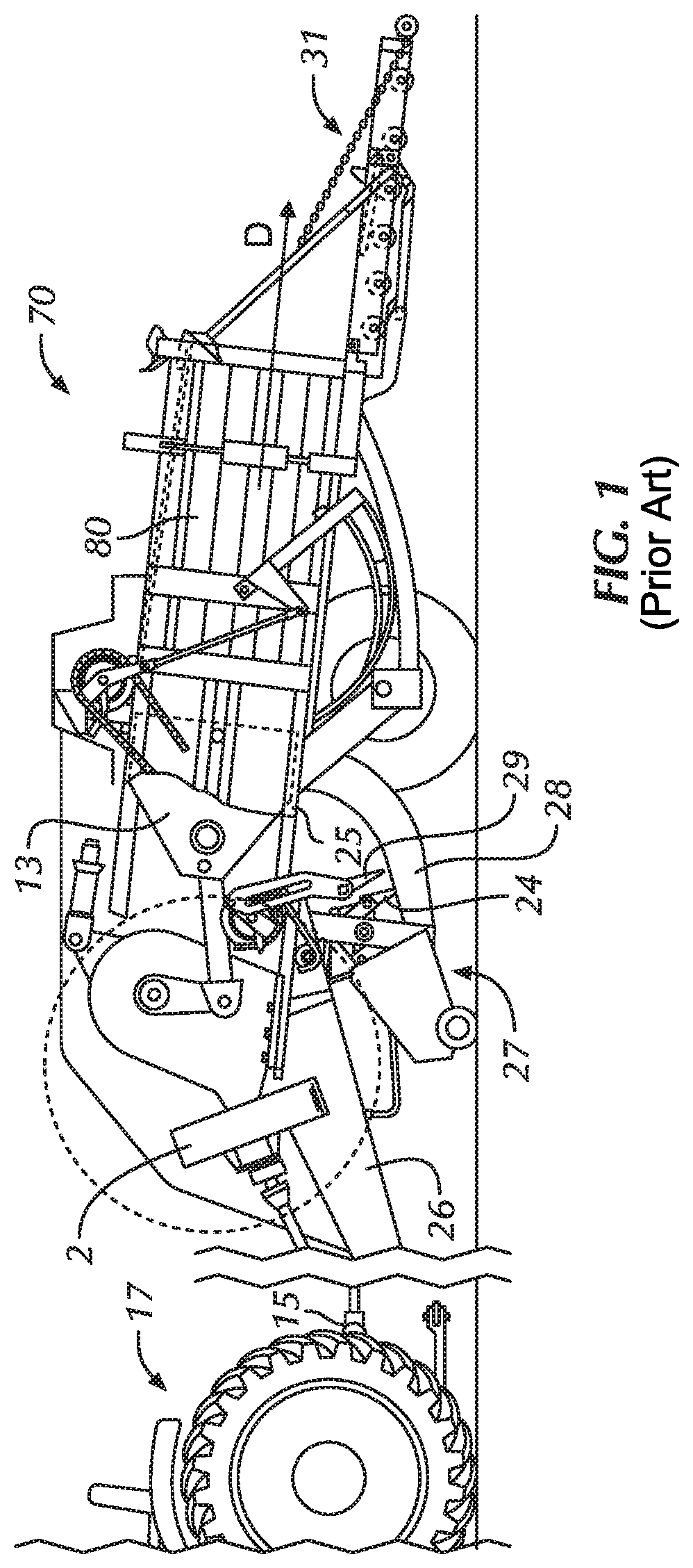
[0125]In a first example, the baler 70 comprises a first sensor 43a (see FIG. 9) for measuring the angular velocity ω as a function of time: ω(t), e.g. a tachometer or a speed sensor, and a second sensor 43b for measuring the angular displacement of the crank as a function of time: θ(t). The first and second sensor 43a, 43b need not be located on the crank 6 itself, but may also be located e.g. on the flywheel 2, or on the shaft 3, running synchronously with the crank 6. In that case, the sensor signals, e.g. the angular position θ or angular velocity ω of the shaft 3 can easily be converted into the angular position and angular velocity of the crank 6 by applying a multiplication factor N, being the ratio of the rotation speed of the shaft 3 and that of the crank 6. FIG. 12 and FIG. 13 show a graph of the angular velocity ω(t) and angular position θ(t) of the crank versus time.
[0126]The sensors 43 in this example provide a continuous time signal ω(t) and θ(t). Before time t0, the b...
example 2
[0137]In a variant of example 1, instead of calculating Efrict and Ecompr of the previous revolution, and predicting Efrict and Ecompr for the next revolution, and checking if the kinetic energy is still large enough for surviving the next revolution, the algorithm may compare the kinetic energy to a predefined threshold energy Ethr instead. The value of this threshold energy may be determined during testing or calibration of a particular baler 70, e.g. under worst case crop conditions, optionally by taking into account a safety margin. Note that according to formula (5), checking if the kinetic energy Ekin is equal to or smaller than a predefined threshold value Ethr, is equivalent to checking if the angular speed w is equal to or smaller than a predefined threshold value ωthr. Note that this value of Ethr may also be calculated from formulas (6) and (7), taking into account realistic values for k21, k22, k31, k32 and ω at which the braking is started. The algorithm of example 2 wo...
example 3
[0138]In a third example, illustrated in FIG. 14, the baler 70 comprises a proximity sensor 43 located at crank angle 270°, which gives a signal when the crank passes the 270° angular position. The brake controller 47 comprises a processor connected to a clock unit and to a memory. When the crank 6 passes the sensor 43 a first time, the sensor 43 gives a signal, and the processor retrieves a first time value t1 from the clock unit, and stores the value in the memory. When the crank passes the sensor 43 the next time, a second time value t2 is retrieved from the clock unit, and also stored in memory. The difference in time is then calculated as:
Δt=t2−t1
[0139]and the (average) angular velocity is calculated as:
ω=2*pi / Δt, where pi is approximately 3.1416
[0140]FIG. 14 gives a graphical representation of this data and the functioning of this algorithm. FIG. 14(a) shows a step-wise approximation of the angular velocity ω(t) of the crank over time, as obtained by this algorithm. Before tim...
PUM
 Abstract
Description
Claims
Application Information
 - R&D Engineer
- R&D Manager
- IP Professional
- Industry Leading Data Capabilities
- Powerful AI technology
- Patent DNA Extraction
Browse by: Latest US Patents, China's latest patents, Technical Efficacy Thesaurus, Application Domain, Technology Topic.
© 2024 PatSnap. All rights reserved.Legal|Privacy policy|Modern Slavery Act Transparency Statement|Sitemap