Check patentability & draft patents in minutes with Patsnap Eureka AI!

Method for detecting a defect on a surface by multidirectional lighting and associated device

a multi-directional lighting and defect detection technology, applied in the field of multi-directional lighting and associated devices for detecting defects on surfaces, can solve the problems of time-consuming and complex surface analysis

Active Publication Date: 2020-05-12
FRAMATOME ANP
View PDF14 Cites 0 Cited by
  • Summary
  • Abstract
  • Description
  • Claims
  • Application Information

AI Technical Summary

Benefits of technology

The technical effect of this patent is to provide a simple and safe method to detect defects on a surface.

Problems solved by technology

The analysis of a surface may be time-consuming and complex.

Method used


Image

  • Method for detecting a defect on a surface by multidirectional lighting and associated device
  • Method for detecting a defect on a surface by multidirectional lighting and associated device

Examples


Embodiment Construction

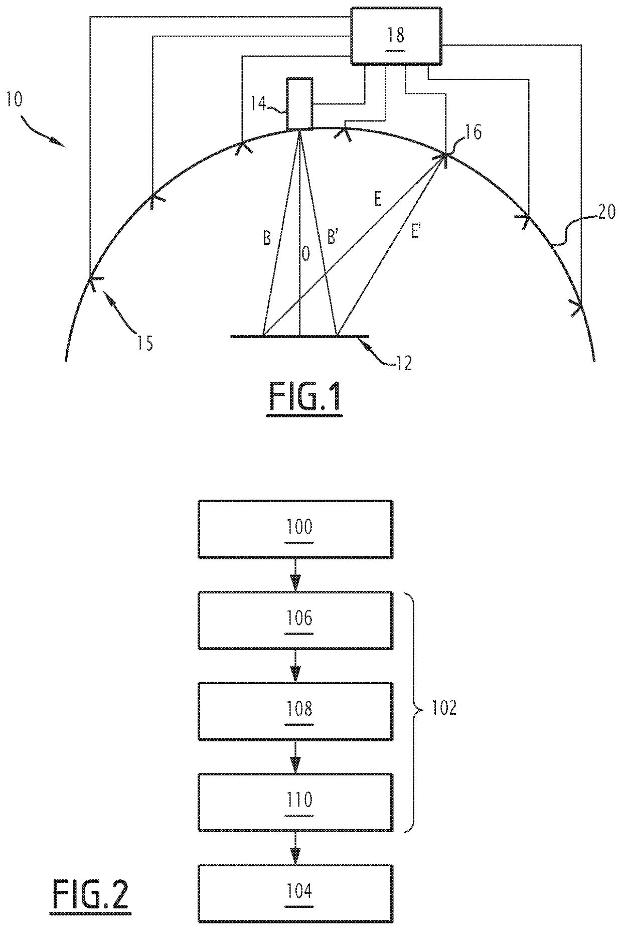
[0043]An example device 10 for detecting a defect on a surface 12 is shown in FIG. 1.

[0044]The detection device 10 includes an optical device 14, a lighting device 15 including a first number of light source(s) 16 and an electronic calculating device 18.

[0045]The optical device 14 has an optical axis aligned with a given optical direction O. It has an acquisition field.

[0046]The optical device 14 is able to acquire an image of the surface 12 along the given optical direction O. The acquisition field coincides with the surface 12 to be inspected, such that the acquired image represents the surface 12.

[0047]For each point of the surface, an observation direction B, B′ is defined between the optical device 14 and the point of the surface 12.

[0048]The acquisition field here is fixed.

[0049]The optical direction O is typically substantially perpendicular to the surface 12. Alternatively, the optical direction O is not substantially perpendicular to the surface 12.

[0050]The optical device ...


PUM

PropertyMeasurementUnit
opticalaaaaaaaaaa
light intensityaaaaaaaaaa
surface imageaaaaaaaaaa

Abstract

A method for detecting a defect on a surface (12) by multidirectional lighting includes acquiring a plurality of images of the surface (12) using an optical device (14) having an optical axis, each image being acquired with a lighting of the surface along a lighting direction (E, E′) given for each point of the surface (12) and an optical direction (O), the images being acquired with different lighting directions (E, E′) or different combinations and / or with different optical directions (O); for each point, calculating a plurality of parameters, the parameters including coefficients of an equation characterizing the response of said point of the surface as a function of the lighting direction (E, E′) and an observation direction (B, B′); and deducing from the calculated parameters whether the surface (12) has a defect at said point.

Description

[0001]The present invention relates to a method for detecting a defect on a surface.[0002]It also relates to an associated detection device.BACKGROUND[0003]One current method consists of acquiring an image or a film of the surface. Said image or film is next viewed by an operator, who indicates the defects that he has identified.[0004]However, the operator may not identify a defect due to lack of attention. Furthermore, the criteria making it possible to judge a defect are subjective, i.e., the definition of what constitutes a defect may vary depending on the operator.[0005]One solution often implemented to offset these problems is to have the film or image viewed by several operators. Furthermore, surface image examples are used in order to show what is or is not a defect.[0006]However, the examples shown are neither exhaustive nor reproducible.[0007]In the event of a defect, experts are consulted. Many discussions between experts then take place, the experts not necessarily agreei...

Claims


Application Information

Patent Timeline
Patent Type & Authority Patents(United States)
IPC IPC(8): G01N21/88G01N21/47
CPCG01N21/474G01N21/8806G01N21/4738G01N2021/8816
Inventor TAGLIONE, MATTHIEUSKOPINSKI, CLÉMENTCAPUT, GAUTIER
Owner FRAMATOME ANP
Features
  • R&D
  • Intellectual Property
  • Life Sciences
  • Materials
  • Tech Scout
  • Unparalleled Data Quality
  • Higher Quality Content
  • 60% Fewer Hallucinations
Learn More