Check patentability & draft patents in minutes with Patsnap Eureka AI!

Toggle fixing

a technology of fixing and screw, which is applied in the direction of fastening means, dowels, mechanical equipment, etc., can solve the problems of screwing in taking more time than pushing, the crosspiece being pressed away from the inaccessible side, and the opening is even harder to find, so as to achieve the effect of being more user-friendly to handl

Active Publication Date: 2020-06-02
FISCHERWERKE ARTUR FISCHER GMBH & CO KG
View PDF18 Cites 1 Cited by
  • Summary
  • Abstract
  • Description
  • Claims
  • Application Information

AI Technical Summary

Benefits of technology

[0008]It is characteristic of the toggle fixing according to the invention that the engagement element has a manipulating element such that it is movable radially outwards relative to the longitudinal axis of the sleeve. According to the invention the engagement element with the manipulating element is configured so that such movement is effected from a rear side of the sleeve remote from the crosspiece, that is to say the engagement element is manipulatable from the accessible rear side facing the user. This enables a screw to be pushed through the screw hole while the engagement element is moved radially to the side by means of the manipulating element, this being referred to as “deactivation” hereinbelow. Once the screw has been inserted in such a way that the front end in the introduction direction abuts the crosspiece, the engagement element can especially be moved radially inwards again or moves independently in that direction in such a way that the thread of the screw is engaged. This is referred to hereinbelow as “activation”. When the screw is screwed in, axial forces can then in turn be transmitted from the screw via the engagement element into the sleeve and from the latter into the thin-walled component. As mentioned, the deactivation allows the screw to be pushed in, which is considerably quicker than rotational insertion.
[0009]In a preferred embodiment, the engagement element is pivotally connected to a main body of the sleeve, with “pivotally” here not being meant narrowly in the sense of a physically exactly defined pivot axis, but, for example, also including the movement of a flexible bar, with a pivot axis approximately in the region of attachment of the flexible bar. The pivot axis is preferably arranged at the end of the engagement element opposite the rear side of the sleeve. In other words, the pivot axis is located to the front of the engagement element, the terms “front” and “rear” here always referring to the introduction direction of the screw. In comparison with the reverse arrangement as known from DE 10 2015 116 426 A1, this has the advantage that the screw is supported significantly more rigidly by the engagement element and, in particular, the engagement element does not yield radially outwards when axial forces are exerted on the screw.
[0010]Preferably the engagement element is resiliently connected to a main body of the sleeve. As compared with the toggle fixing known from the specification DE 10 2015 116 426 A1, this not only makes it possible to adapt to different screw diameters, but especially enables automatic resetting to take place radially inwards for activation after a deactivation.

Problems solved by technology

If the screw were arranged to be simply pushed through the sleeve, an axial force on the screw could result in the crosspiece being pressed away from the inaccessible side of the thin-walled component.
If the screw does not directly encounter the opening having the internal thread, the force has the effect that the crosspiece may shift position in such a way that the opening is even harder to find.
A disadvantage of the known solution is that screwing-in requires more time than pushing-in.

Method used


Image

  • Toggle fixing
  • Toggle fixing

Examples


Embodiment Construction

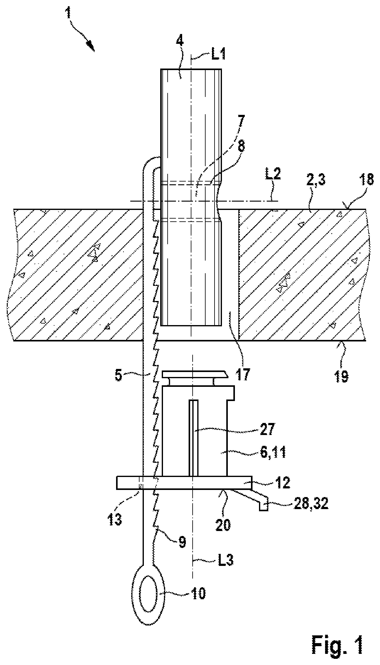
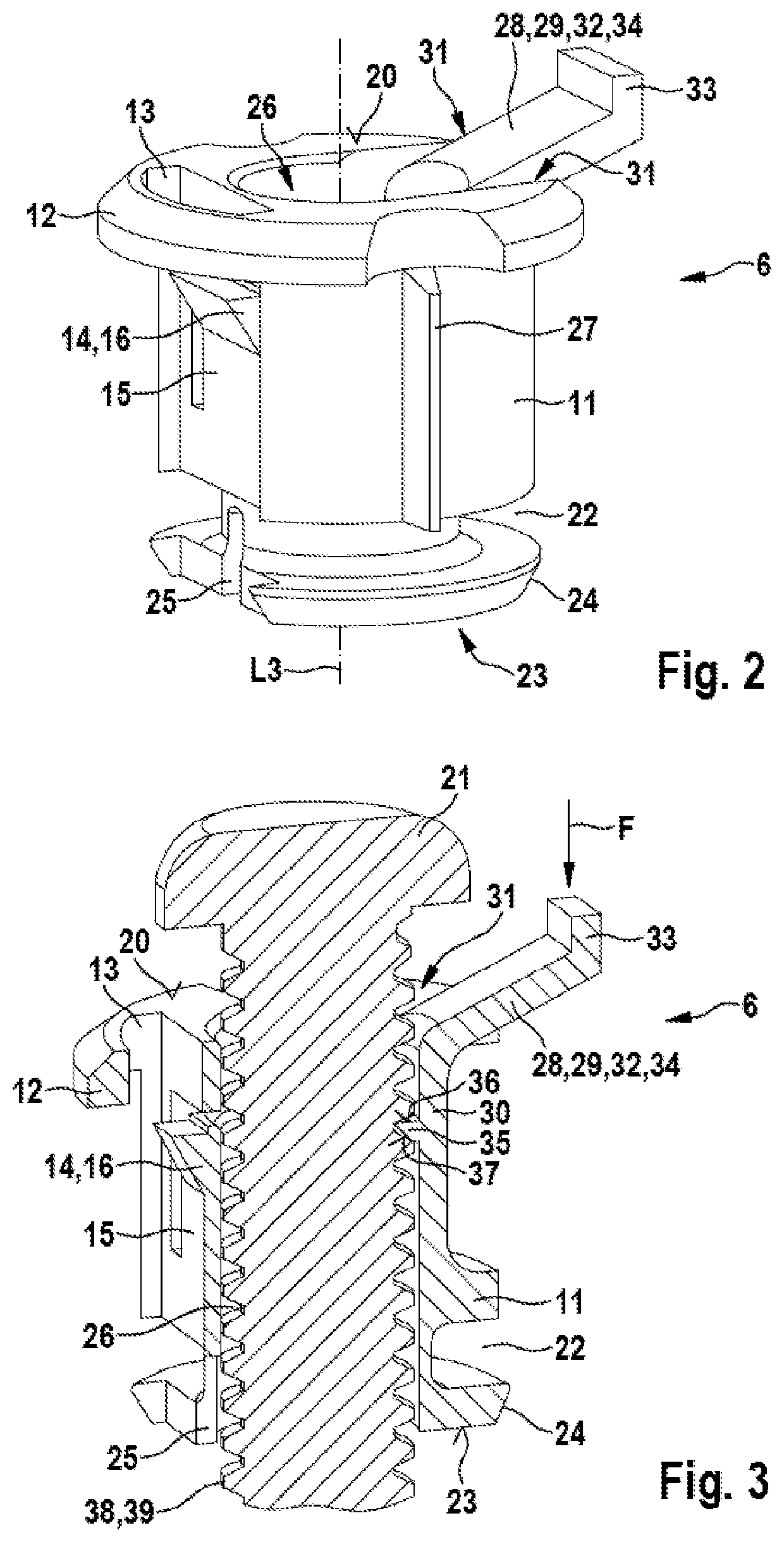
[0019]The toggle fixing 1 according to the invention shown in the Figures for fixing an article (not shown) to a thin-walled component 2, in this case a plasterboard panel 3, has a substantially cylindrical crosspiece 4 made of plastics material, a strip 5 which is integrally connected to the crosspiece 4, and a sleeve 6 made of plastics material which is arranged on the strip 5.

[0020]The crosspiece 4 serves for engaging behind the plasterboard panel 3. It extends along a crosspiece longitudinal axis L1 and has in the centre an opening 7 having an internal thread 8. The opening 7 extends along an opening longitudinal axis L2 which runs perpendicularly to the crosspiece longitudinal axis L1. In other words, the opening 7 passes transversely through the crosspiece 4. The strip 5 is attached to the crosspiece 4 next to the opening 7 and in the relaxed state (not shown) extends parallel to the opening longitudinal axis L2, that is to say perpendicular to the crosspiece longitudinal axis...


PUM


Abstract

A toggle fixing for fixing an article to a thin-walled component, having a crosspiece for engaging behind the component, which crosspiece has an opening for receiving a screw. Connected to the crosspiece there is an elongated strip having a displaceable sleeve which has a screw hole for passage of the screw. The sleeve has an engagement element for threaded engagement of a screw in order that the latter does not unintentionally tilt the crosspiece during mounting. In order to provide quick insertion of a screw, the engagement element has a manipulating element such that the engagement element is movable radially outwards relative to the longitudinal axis, and the engagement element is manipulatable from a rear side of the sleeve emote from the crosspiece.

Description

CROSS-REFERENCE TO RELATED APPLICATIONS[0001]This application claims priority under 35 USC § 119 to German Patent Application No. 10 2017 113 639.8, filed on Jun. 21, 2017, the entire disclosure of which is incorporated herein by reference.TECHNICAL FIELD[0002]The invention relates to a toggle fixing.BACKGROUND ART[0003]A generic toggle fixing is known from the specification DE 10 2015 116 426 A1. The toggle fixing is used for fixing an article to a thin-walled component, for example to a plasterboard panel, as used in dry walling for producing walls and for cladding ceilings. A “thin-walled” component can, however, also be the wall of a vertically perforated brick or the wall of an item of ceramic sanitaryware, this list not being exhaustive. In the installed state, the rear side of the component is usually not accessible, but there is a cavity behind the component. If the component is, for example, a plasterboard panel and an article is to be fixed thereto, first of all a hole is ...

Claims


Application Information

Patent Timeline
Patent Type & Authority Patents(United States)
IPC IPC(8): F16B21/00F16B13/08
CPCF16B13/0808
Inventor DALY, AARON
Owner FISCHERWERKE ARTUR FISCHER GMBH & CO KG
Features
  • R&D
  • Intellectual Property
  • Life Sciences
  • Materials
  • Tech Scout
  • Unparalleled Data Quality
  • Higher Quality Content
  • 60% Fewer Hallucinations
Learn More