Ratcheting take-up device

a ratcheting and take-up technology, applied in the direction of rod connections, screws, building repairs, etc., can solve the problems of lack of a means of compensating for slack that builds up, and achieve the effect of quick insertion and minimal risk of jamming the take-up devi

Active Publication Date: 2014-11-11
SIMPSON STRONG TIE
View PDF308 Cites 19 Cited by
  • Summary
  • Abstract
  • Description
  • Claims
  • Application Information

AI Technical Summary

Benefits of technology

[0009]A further advantage of the present invention is that the housing and insert segments are shaped and arranged to allow a tie rod to be quickly inserted through the inner bore formed by the insert segments by pushing the tie rod up through the bore. When a tie rod is first inserted up into the housing, the upward movement of the tie rod forces the insert segments apart from a constricted position—the constriction preferably caused by the downward force of gravity and possibly by a compression member placed above the insert segments, combined with the narrowing in the lower portion of the outer bore of the housing—to the width of the tie rod. The interface between the surfaces of the tie rod and the insert segments creates a ratcheting action as the tie rod is pushed up and the insert segments move up and out laterally, allowing the tie rod to be inserted as far as needed into the housing for installation. When the building shrinks, the relative movement of the tie rod and the housing is similar to movement during installation. The relative upward movement of the rod with respect to the housing pushes the insert segments up and out laterally, and gravity and any relative downward movement of the tension rod as well as the usual tension that is placed on the rod once it is installed pulls the insert segments downwardly and inwardly in combination with the narrowing of the outer bore of the housing and thus against the rod, holding it with respect to the housing.
[0010]A further object of the present invention is to provide insert segments that are made with flat tops and bottom edges and in the preferred embodiment are compressed by a member with a flat surface so that it allows tie rods to be inserted with a minimal risk of jamming the take-up device because the insert segments are held in place by a flat, hard washer above, which interface with flat surfaces at the tops of the insert segments to stabilize them as they expand away from and constrict towards the central vertical axis of the device. Another object of the present invention is to provide the housing with a small ledge which interfaces with the bottom edges of the insert segments to stabilize them as they expand away from and constrict towards the central vertical axis of the device.

Problems solved by technology

The principal shortcoming of the system of the '314 patent is the lack of a means of compensating for slack that builds up in the system as the wood structural members shrink over time.

Method used


Image

  • Ratcheting take-up device
  • Ratcheting take-up device
  • Ratcheting take-up device

Examples


Embodiment Construction

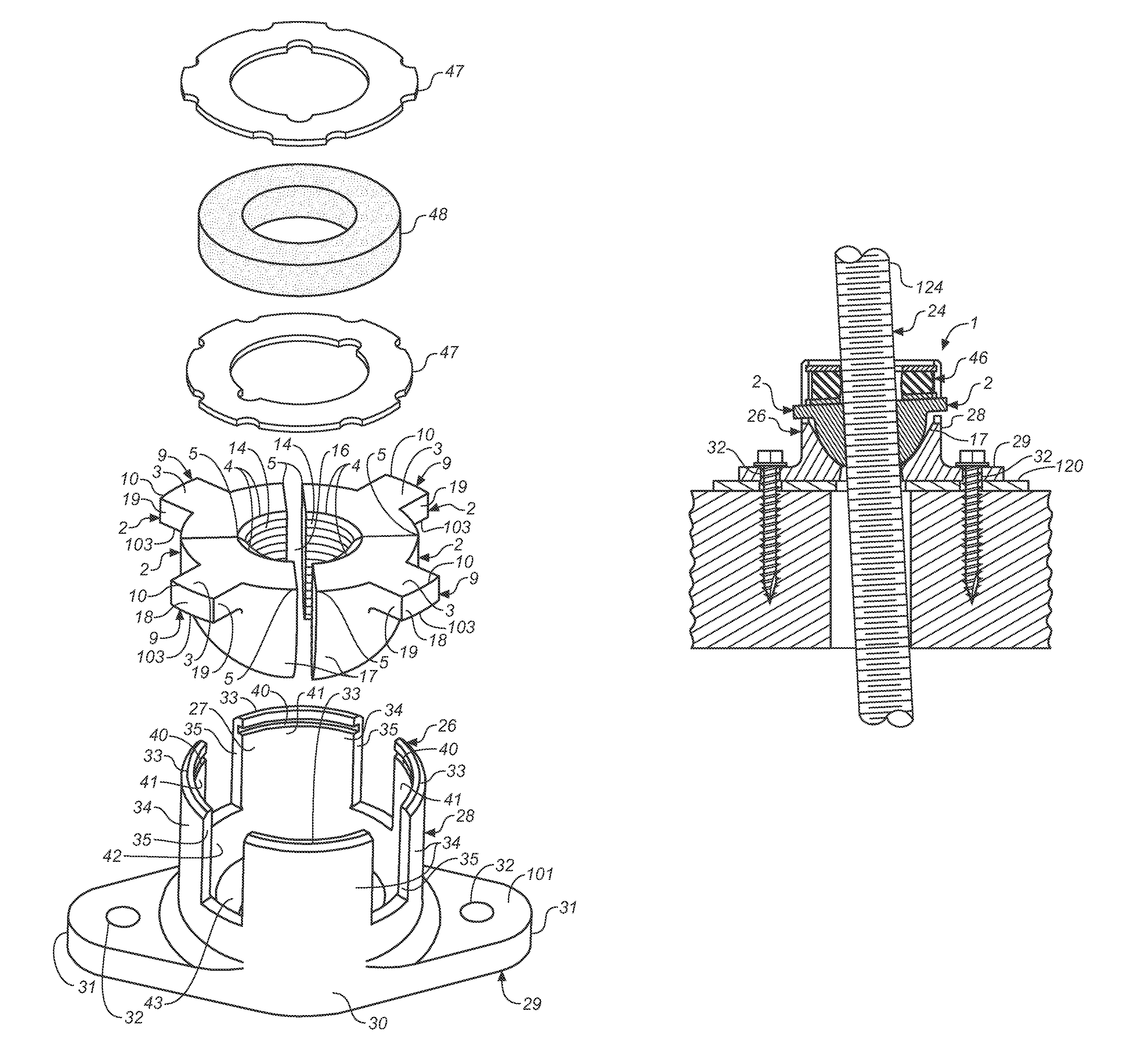
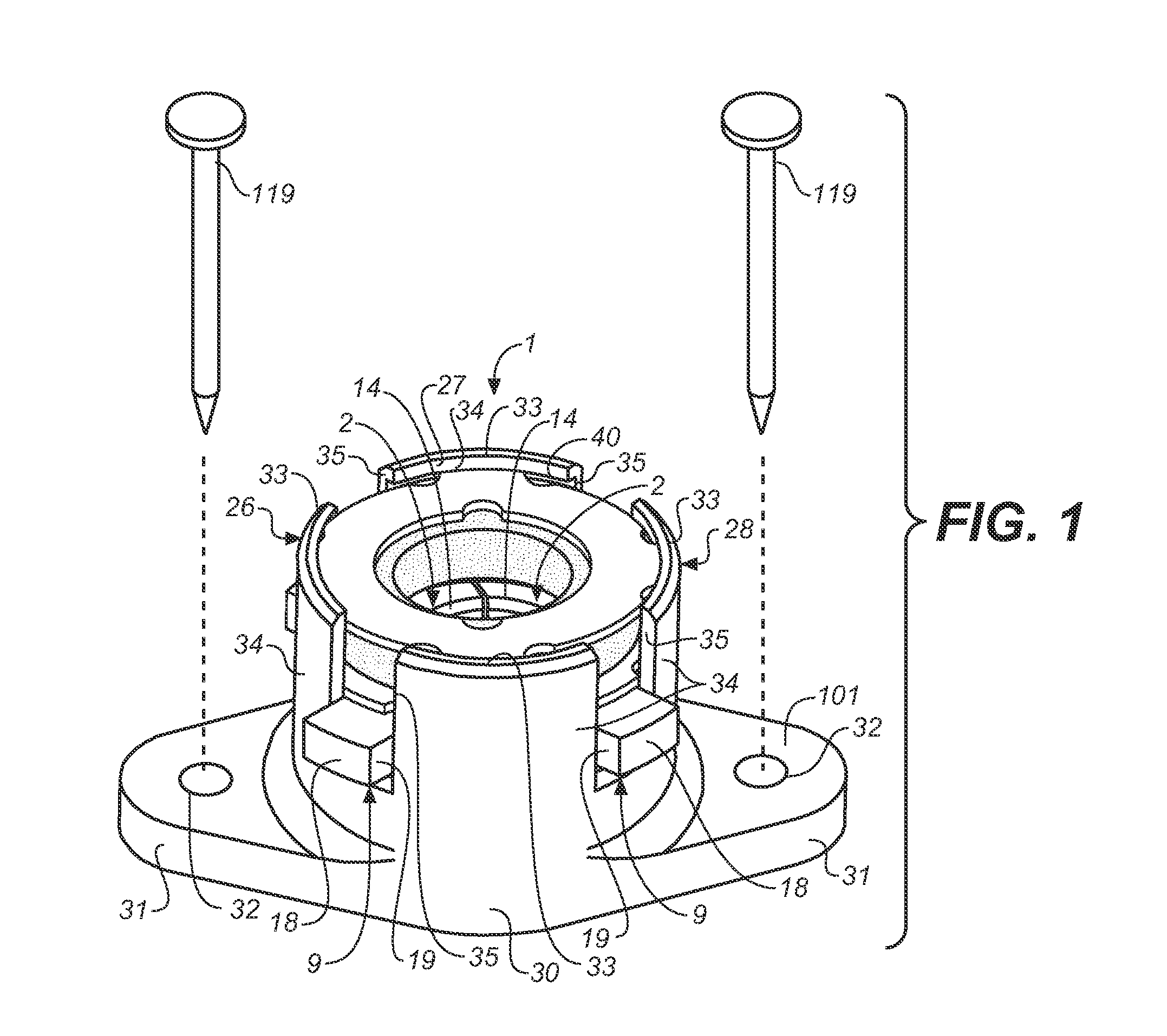
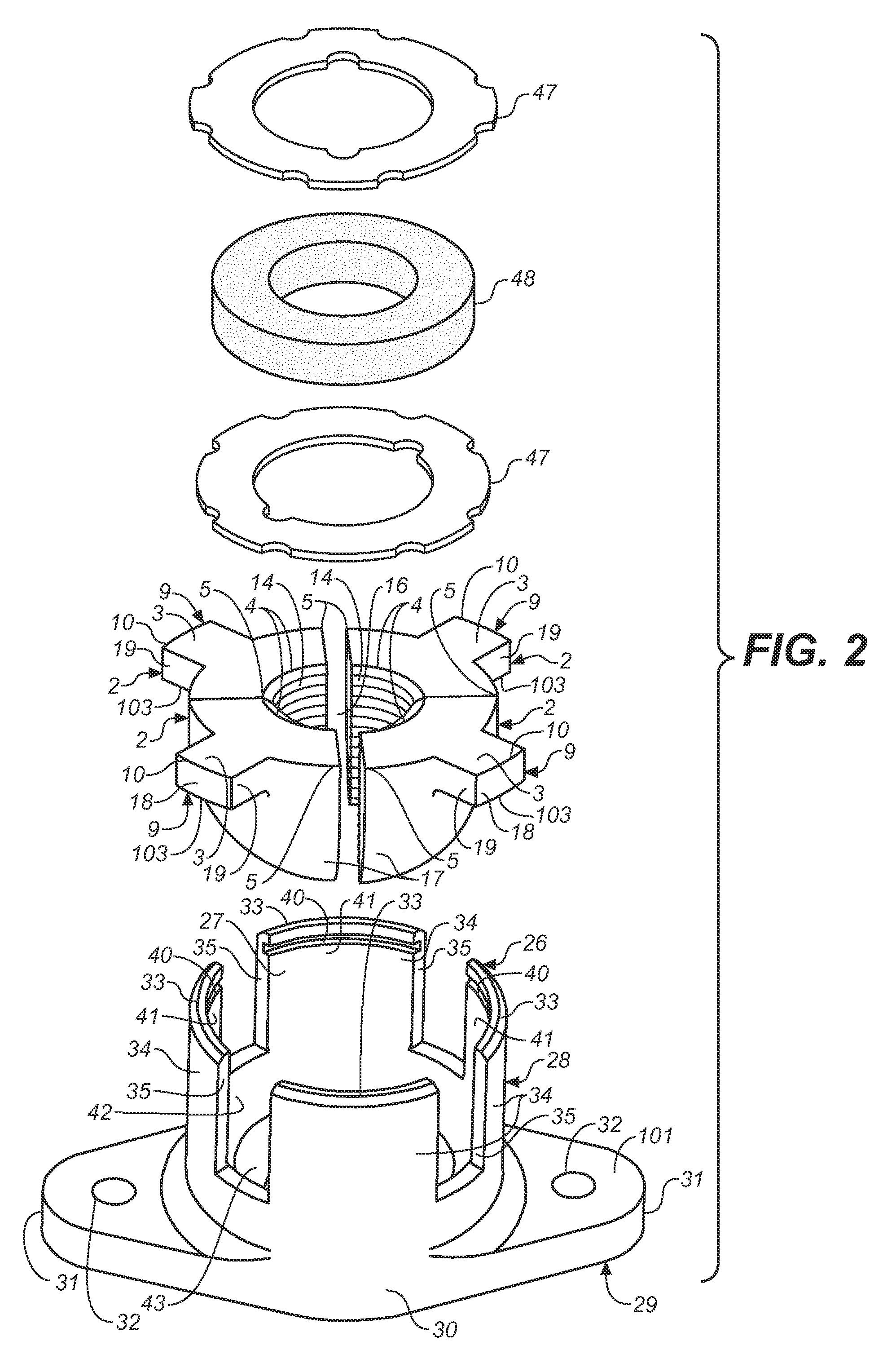
[0032]For clarity and convenience, the take-up device 1 of the current invention is described in a single, most common, orientation (except as noted otherwise) in which a top faces up and a bottom faces down. The take-up device 1 can, nevertheless, be installed in essentially any orientation, so that a top can face down or to the side and a bottom can face up or to the side.

[0033]As best shown in FIGS. 2 and 11, the take-up device 1 of the present invention preferably has four insert segments 2 arranged sectionally around an inner bore 16. Greater or lesser numbers of insert segments 2 are possible, but four is preferred. The insert segments 2 are designed to grasp a preferably vertical tie rod or threaded bolt 24. Preferably, vertical tie rod 24 is a least threaded where it is grasped by insert segments 2. Vertical tie rod 24 can be wholly threaded, partially threaded, or unthreaded, although if is unthreaded it is preferable to have a grooved surface that can mate with similar gro...


PUM


Abstract

A ratcheting take-up device that compensates for imperfect alignment in a tie rod continuity system in the frame of a building wall. The upper ends of the tie rods are tightly clamped within the take-up device by domed segments inserted in a bowl-shaped housing. The segments are also forced together by a compression member in the housing. The domed shape of the segments and the bowl shape of the housing cooperate so that the segments can rotate in any direction to accommodate tie rods that are not perfectly vertical, without a corresponding loss of strength in the connection.

Description

BACKGROUND OF THE INVENTION[0001]The present invention relates generally to building construction and reinforcement, and specifically to a continuity system that resists tension from wind uplift forces or overturning forces from wind or seismic events while compensating for the downward settling of buildings caused by shrinkage of wooden members. Most specifically, the present invention relates to a ratcheting take-up device that reduces slack due to wood shrinkage and building settling in a holdown system of continuous rods, eases installation and compensates for imperfectly aligned rods.[0002]A continuity system is a secondary support system that ties walls or other building elements together and resists lateral overturning forces or uplift forces from events such as earthquakes or strong winds. Earthquake and wind forces produce overturning and uplift loads in the building, which load the building elements in overturning or uplift with respect to the building foundation. A contin...

Claims


Application Information

Patent Timeline
Patent Type & Authority Patents(United States)
IPC IPC(8): E04C5/08
CPCE04B2001/2688E04B1/26E04B2001/3583Y10T403/32541Y10T403/551
Inventor GRAY, DANIEL M.MCGURTY, LISA M.WERT, BRYAN DAVIDSTRAWN, THOMAS MAXWELL
Owner SIMPSON STRONG TIE
Why Eureka
Try Eureka