Projection device and interface device having mirror which reflects light other than zero-order light toward a projection lens

a technology of projection lens and projection lens, which is applied in the field of projection device and interface device using a spatial mod, can solve the problems of reducing luminance, reducing power efficiency, and not being able to completely remove zero-order light, etc., and achieve the effect of not reducing luminan

Active Publication Date: 2020-06-02
NEC CORP
View PDF14 Cites 0 Cited by
  • Summary
  • Abstract
  • Description
  • Claims
  • Application Information

AI Technical Summary

Benefits of technology

[0021]According to the present invention, it is possible to project an image in which zero-order light is removed, without adding extra modulation elements or pixels, without applying distortions, and without reducing luminance.

Problems solved by technology

However, phase modulation type requires a light source configured to emit coherent light, and superiority on power efficiency may be lost in a case where a natural picture is displayed.
However, it is not possible to completely remove the zero-order light 102 in an actual system.

Method used


Image

  • Projection device and interface device having mirror which reflects light other than zero-order light toward a projection lens
  • Projection device and interface device having mirror which reflects light other than zero-order light toward a projection lens
  • Projection device and interface device having mirror which reflects light other than zero-order light toward a projection lens

Examples


first example embodiment

[0049]First of all, a projection device according to the first example embodiment of the present invention is described with reference to the drawings.

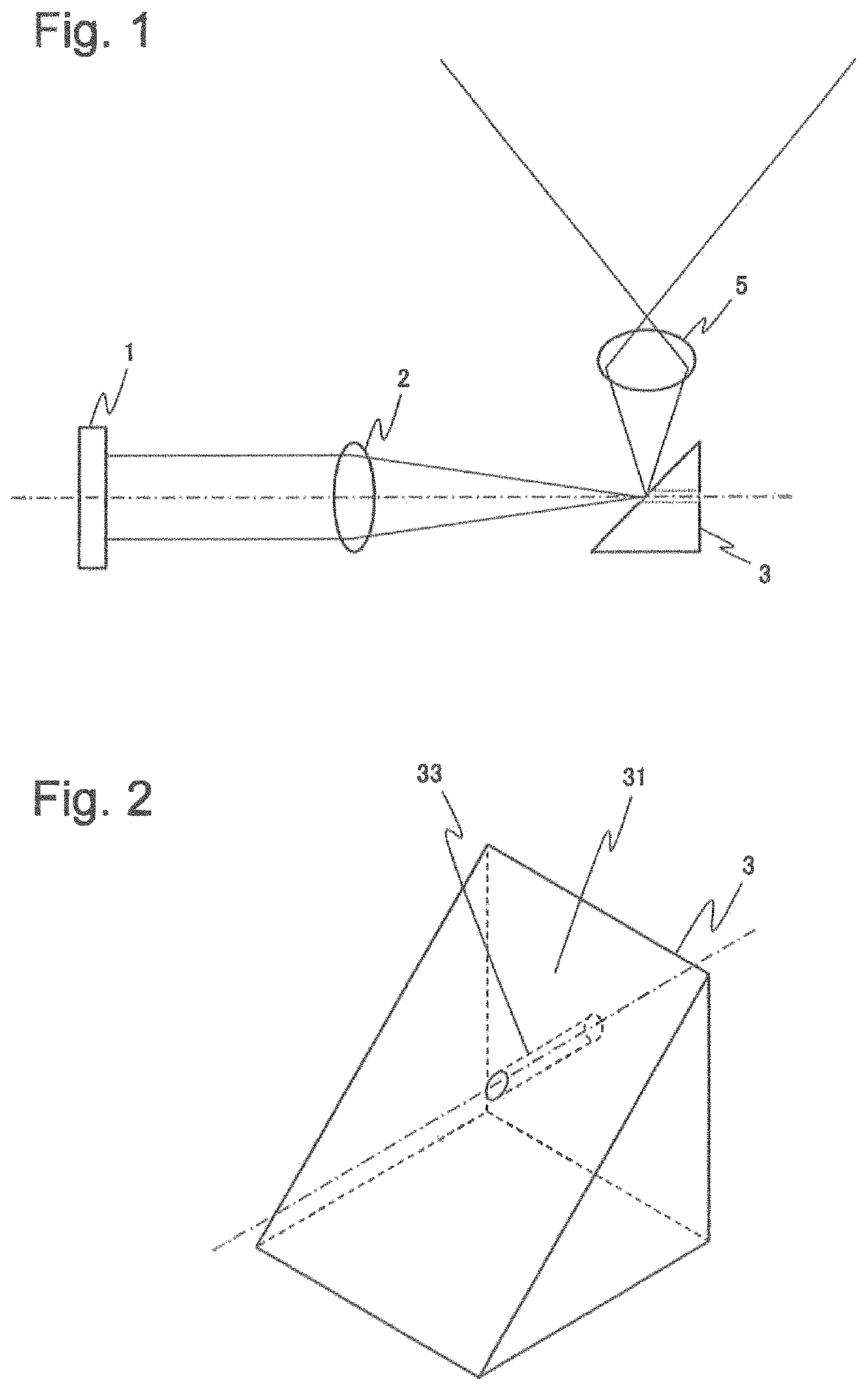
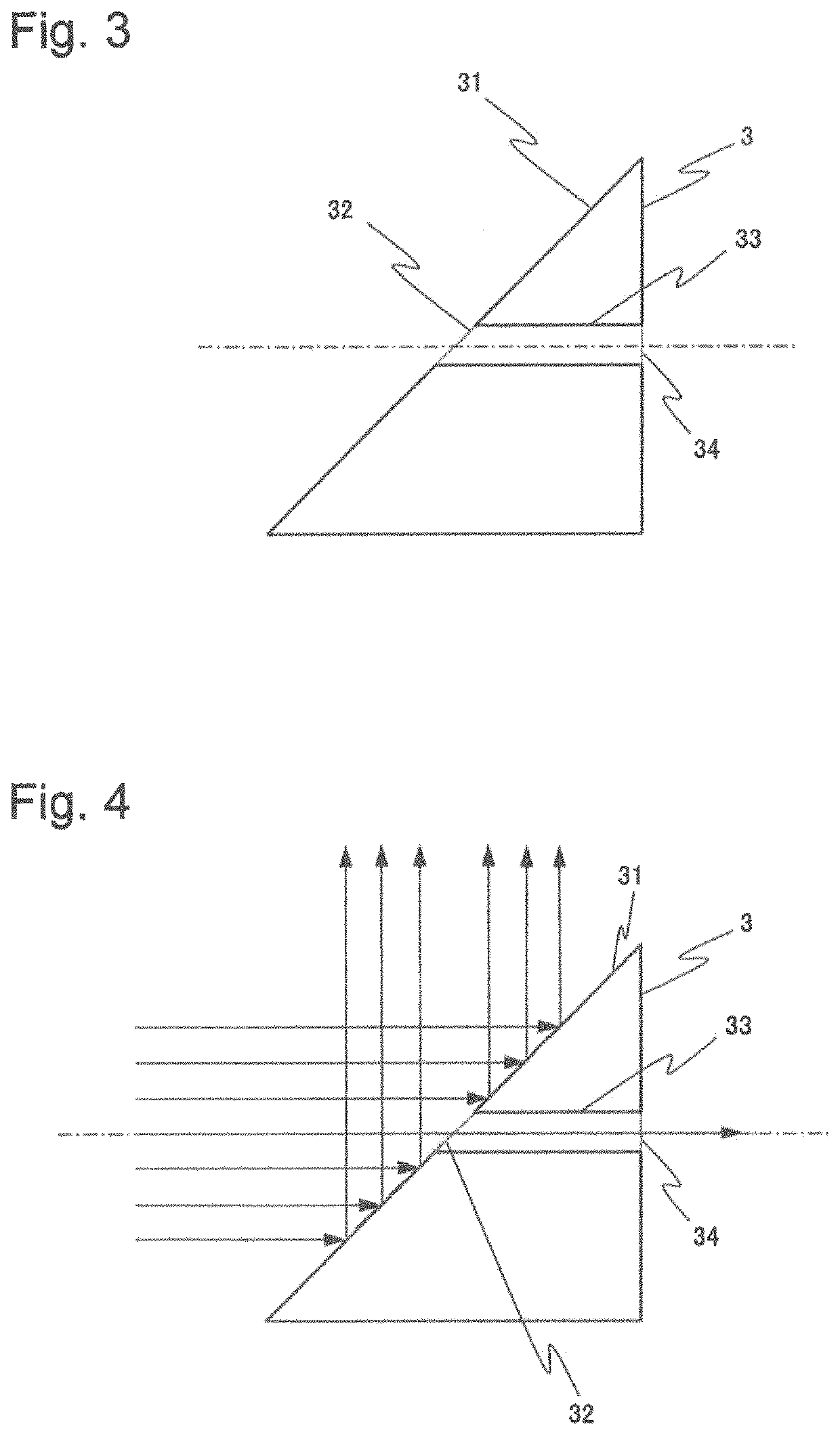
[0050]FIG. 1 is a diagram illustrating a configuration of a projection device according to the example embodiment. The projection device according to the example embodiment includes a phase modulator 1, a Fourier transform lens 2, a mirror 3, and a projection lens 5.

[0051]The phase modulator 1 is a modulation element of phase modulation type, which is configured to allow incidence of laser light emitted from an unillustrated light source, and to modulate the phase of the incident laser light. The phase modulator 1 outputs modulated laser light toward the Fourier transform lens 2.

[0052]The phase modulator 1 includes a plurality of light receiving areas arranged in a lattice. A control means (not illustrated) controls to change a parameter that determines a difference between a phase of laser light incident on each light receiving area,...

modification examples

[0071]In this section, modification examples of the mirror to be used in the projection device according to the example embodiment are described.

[0072]First of all, a first modification example is described.

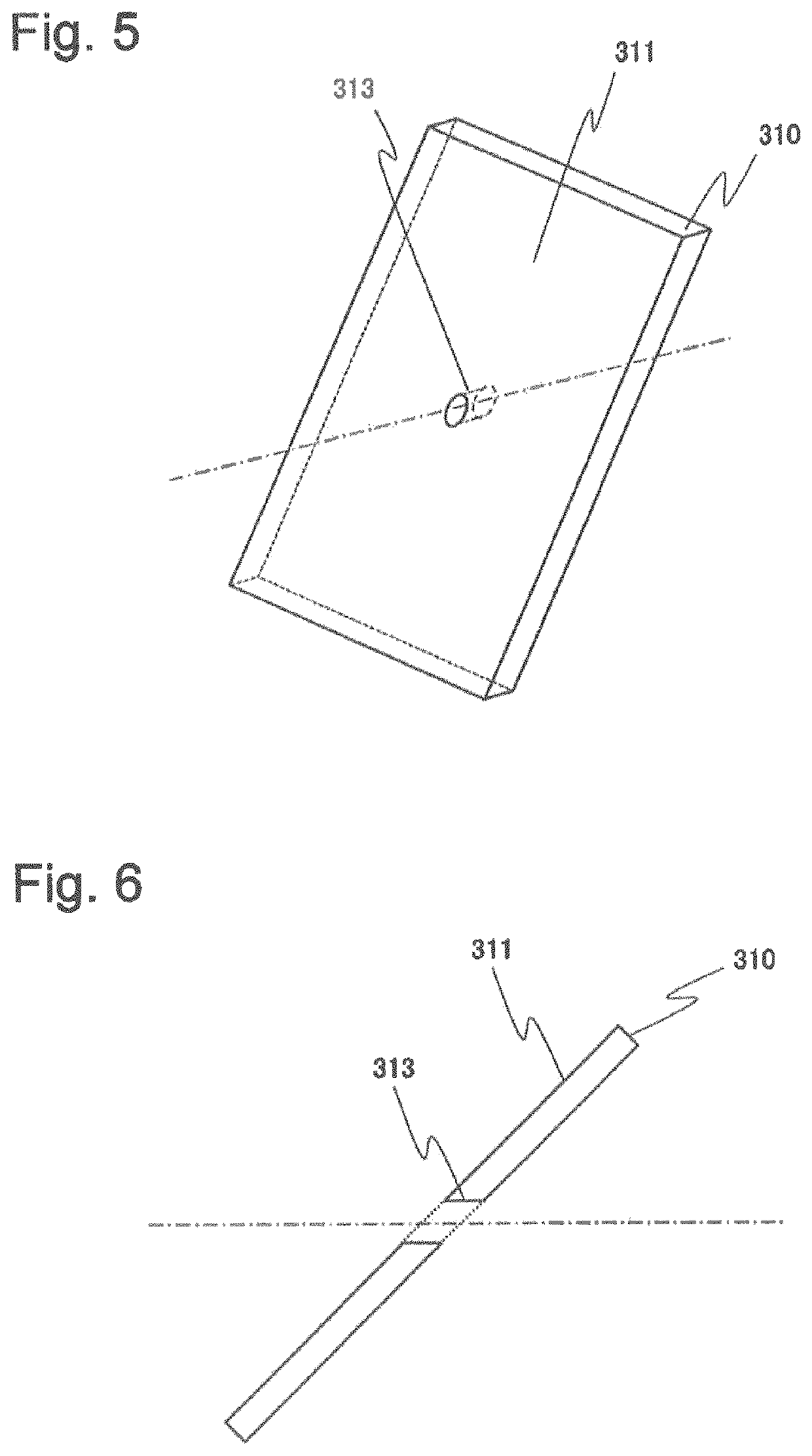
[0073]FIG. 5 illustrates a perspective view of a mirror 310 in the first modification example. Further, FIG. 6 illustrates a sectional view of the mirror 310, which is cut perpendicularly to a reflection surface 311 by using an advancing axis of zero-order light as a cutting line.

[0074]As illustrated in FIG. 5 and FIG. 6, the mirror 310 in the first modification example has a plate shape. At least one of primary surfaces of the mirror 310 is the reflection surface 311. A through-hole 313 through which zero-order light enters is formed in the reflection surface 311. The through-hole 313 passes through up to a surface facing the reflection surface 311. Therefore, zero-order light incident in the through-hole is not reflected on the reflection surface 311 of the mirror 310. On the o...

second example embodiment

[0092]Next, a mirror 350 to be used in a projection device according to a second example embodiment of the present invention is described using FIG. 11 and FIG. 12. Note that a configuration of the projection device according to the example embodiment except for the mirror 350 is the same as in the first example embodiment, and therefore, description thereof is omitted.

[0093]As illustrated in FIG. 11 and FIG. 12, the mirror 350 according to the example embodiment includes a thin-film mirror 351 on a primary surface of a substrate 352 made of glass. A hole 353 is formed in a portion of the thin-film mirror 351 where zero-order light impinges.

[0094]The thin-film mirror 351 may reflect light of all wavelengths to be incident, or may reflect light of a part of the wavelengths, for instance. The thin-film mirror 351 is implemented by a metal thin film such as aluminum or silver, a dielectric film, or the like, for instance. The thin-film mirror 351 may also be implemented as a dichroic m...


PUM

PropertyMeasurementUnit
diameteraaaaaaaaaa
opening diameteraaaaaaaaaa

Abstract

In order to project an image excluding zero-order light without adding extra modulation elements or pixels, without applying distortions, and without reducing luminance, a projection device includes: a phase modulator that modulates the phase of incident laser light; a Fourier transform lens that performs Fourier transformation on laser light, whose phase is modulated by the phase modulator; a mirror disposed on an image formation surface by the Fourier transform lens, and configured to reflect the laser light subjected to Fourier transformation by the Fourier transform lens; and a projection lens that enlarges the light reflected by the mirror and projects the light as projected light. The mirror guides zero-order light included in the Fourier-transformed laser light in a direction different from a direction of the projection lens, and reflects the light excluding zero-order light toward the projection lens.

Description

CROSS-REFERENCE TO RELATED PATENT APPLICATIONS[0001]This application is a National Stage Entry of International Application No. PCT / JP2016 / 000691, filed Feb. 10, 2016, which claims priority from Japanese Patent Application No. 2016-026460, filed Feb. 13, 2015. The entire contents of the above-referenced applications are expressly incorporated herein by reference.TECHNICAL FIELD[0002]The present invention relates to a projection device and an interface device. In particular, the present invention relates to a projection device and an interface device using a spatial modulator of phase modulation type.BACKGROUND ART[0003]In recent years, development on an interface device incorporated with a projector and a camera has progressed. In such an interface device, an image is projected from a projector on a projected surface, and a position or motion of a hand or fingers of an operator with respect to the projected image is detected by a camera to realize interactive motion. NPL 1 discloses...

Claims


Application Information

Patent Timeline
Patent Type & Authority Patents(United States)
IPC IPC(8): G01N21/17G02B26/06H04N5/74H04N9/31G02F1/13G02B26/08G02B27/46G02B5/04
CPCH04N9/3173G01N21/17G02B26/06H04N9/315G02F1/13H04N5/7416H04N9/3155H04N9/3194G02B26/0808G02B27/46G01N2021/1761G02B5/04
Inventor OKUMURA, FUJIO
Owner NEC CORP
Why Eureka
Try Eureka