
Oled Driver and Lighting Apparatus Equipped with the Same

a technology of lighting apparatus and driver, which is applied in the direction of electric variable regulation, process and machine control, instruments, etc., can solve the problems of difficulty in setting the switching frequency to such a high frequency, and the element cannot emit enough light, so as to achieve the effect of not reducing the luminance of the elemen

Inactive Publication Date: 2009-08-27
MATSUSHITA ELECTRIC WORKS LTD
View PDF7 Cites 3 Cited by
  • Summary
  • Abstract
  • Description
  • Claims
  • Application Information

AI Technical Summary

Benefits of technology

[0006]It is an object of the present invention to raise a frequency of voltage periodically applied to at least one organic electroluminescence element without reducing luminance of the element.
[0007]In order to drive at least one organic electroluminescence element, an OLED driver of the present invention comprises a direct-current power source and a dimmer. The source alternately applies first voltage and second voltage to the element. The first voltage is approximately equal to drive voltage of the element, while the second voltage is lower than the first voltage and higher than barrier voltage of the element. The dimmer controls the source so as to change a ratio of a first term to a second term to dimm the element. The first term is a period of time for which the first voltage is applied to the element. The second term is a period of time for which the second voltage is applied to the element. In this structure, the element is supplied with the second voltage higher than the barrier voltage of the element during the second term. Accordingly, when the second term is switched to the first term, the response of the element can be improved.
[0010]In other aspect of the present invention, the driver comprises a means that calculates the second voltage based on voltage applied to the element and an electric current flowing through the element when the element emits light. In case of this invention, the response of the element can be optimized and it is possible to more raise a frequency of voltage periodically applied to the element.

Problems solved by technology

However, in case that the element is supplied with square-wave voltage of which polarity is periodically inverted, it is difficult to set the switching frequency to such a high frequency.
Accordingly, there is a possibility that the element cannot emit enough light.

Method used


Image

  • Oled Driver and Lighting Apparatus Equipped with the Same
  • Oled Driver and Lighting Apparatus Equipped with the Same
  • Oled Driver and Lighting Apparatus Equipped with the Same

Examples


first embodiment

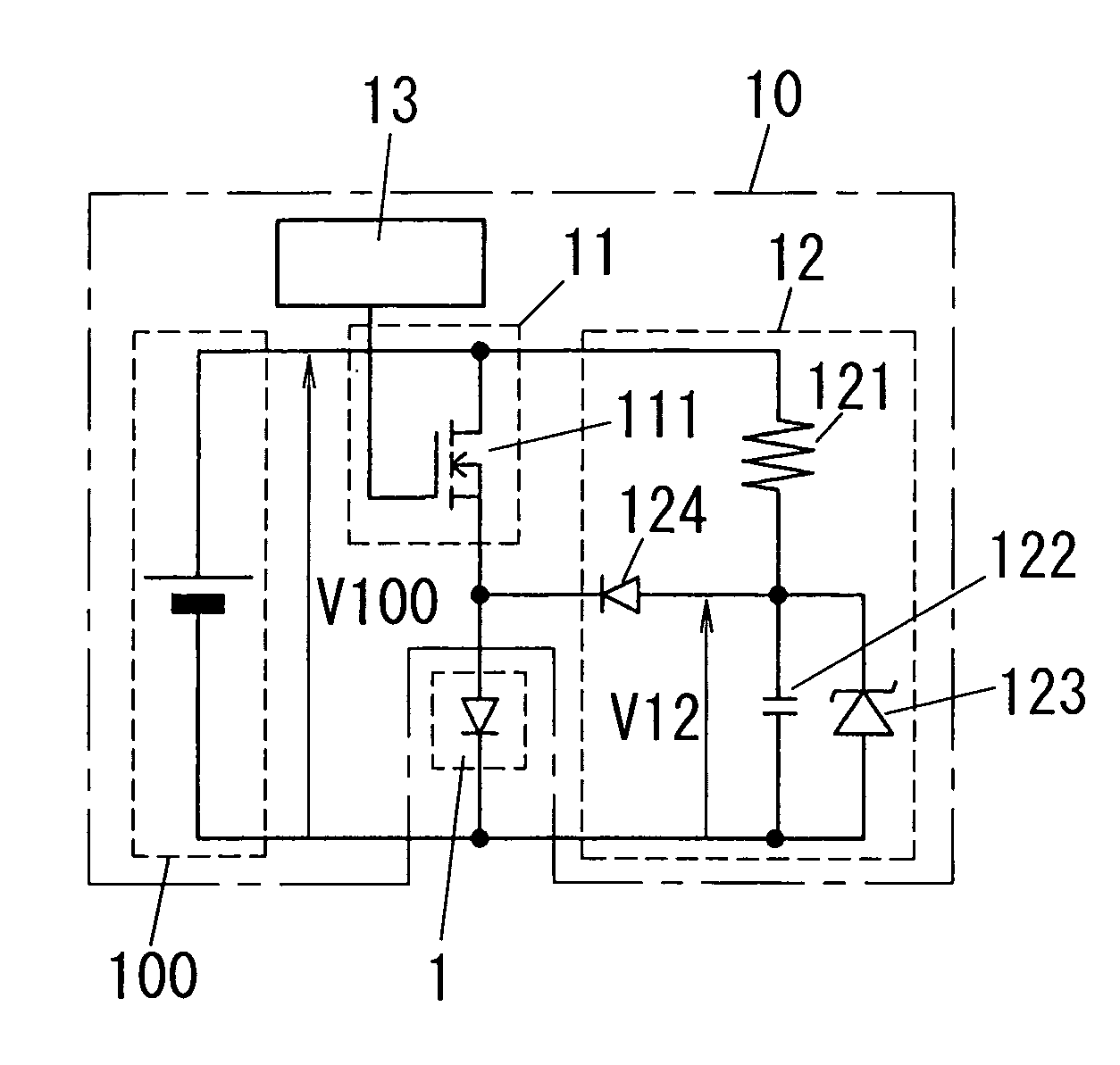
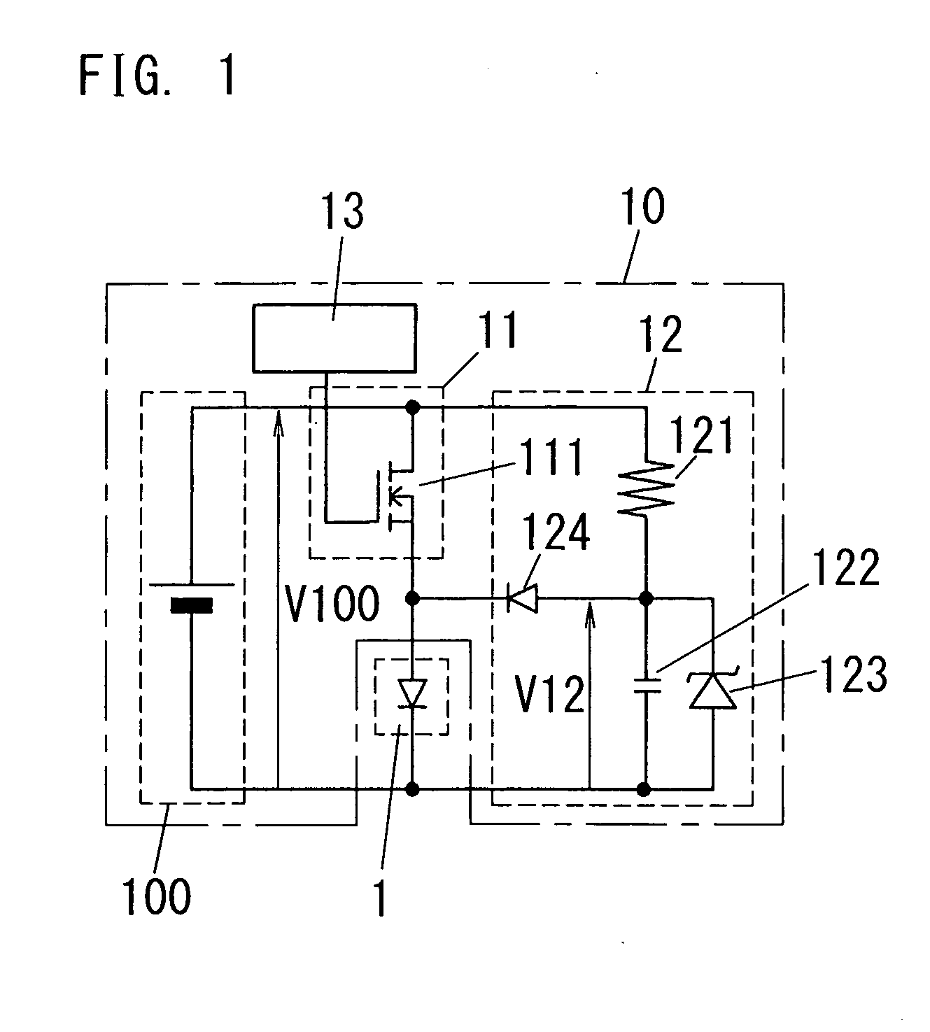
[0020]FIG. 1 shows a first embodiment according to the present invention, namely lighting apparatus. The apparatus is equipped with at least one organic EL element (OLED) 1 and an OLED driver 10 for driving the element 1.

[0021]The organic EL element 1 is formed of an emission layer (an organic thin film) and a pair of electrodes between which the layer is sandwiched from the both surfaces of the layer. The element 1 emits light when electrons injected from one electrode as a cathode recombine with holes injected from other electrode as an anode in the layer.

[0022]The OLED driver 10 has a direct-current power source that is formed of a main power circuit 100, a first voltage supply circuit 11 and a second voltage supply circuit 12 as well as having a dimmer 13. The driver also generates square-wave voltage of which polarity is not inverted to apply the voltage across the element 1.

[0023]The main power circuit 100 is a direct-current power source and generates a first voltage V100 tha...

second embodiment

[0030]The present invention is not limited to the OLED driver 10 formed of each circuit as shown in FIG. 1. For example, the invention may be an OLED driver 20 as shown in FIG. 4. This driver has a direct-current power source formed of a main power circuit 200, a first voltage supply circuit 21 and a second voltage supply circuit 22 as well as having a dimmer 23. The driver 20 also drives at least one organic EL element 2 like that in FIG. 1. The driver 20 in the modified embodiment is now explained as the present invention.

[0031]The main power circuit 200 is formed of a diode bridge 201 as a full wave rectifier that rectifies alternating-current power of a commercial power source AC into pulsating direct current power; and a smooth capacitor 202 that smoothes voltage of the pulsating direct current power. This circuit generates higher voltage than the (emission) drive voltage of the element 2.

[0032]The first voltage supply circuit 21 is configured to convert the voltage across the ...

third embodiment

[0037]FIG. 5 shows a third embodiment according to the present invention, namely lighting apparatus. The apparatus has at least one organic EL element (OLED) 3 and an OLED driver 30 for driving the element 3.

[0038]The OLED driver 30 has a direct-current power source that is formed of a main power circuit 300, a first voltage supply circuit 31 and a second voltage supply circuit 32 as well as having a dimmer 33, a current detector 34 and a second voltage adjuster 35. The driver generates square-wave voltage of which polarity is not inverted to apply the voltage to the element 3.

[0039]The main power circuit 300 is formed of a diode bridge 301 as a full wave rectifier that rectifies alternating-current power of a commercial power source AC into pulsating direct current power; and a smooth capacitor 302 that smoothes voltage of the pulsating direct current power. The circuit 300 generates higher voltage than the (emission) drive voltage of the element 3.

[0040]The first voltage supply ci...


PUM


Abstract

An OLED driver for driving at least one organic electroluminescence element and lighting apparatus equipped with the driver. The driver has a direct-current power source and a dimmer. The source alternately applies first voltage and second voltage across the element. The first voltage is approximately equal to drive voltage of the element. The second voltage is lower than the first voltage and higher than barrier voltage of the element. The dimmer controls the source so as to change a ratio of a first term to a second term to dimm the element. The first term is a period of time for which the first voltage is applied across the element. The second term is a period of time for which the second voltage is applied across the element.

Description

TECHNICAL FIELD[0001]The invention relates to generally OLED drivers and more particularly to an OLED driver for driving at least one organic electroluminescence element and lighting apparatus equipped with the driver.BACKGROUND ART[0002]In this sort of lighting apparatus, at least one organic electroluminescence element is driven at low drive voltage (e.g., about a few to 10 s V) in comparison with discharge lamps. The element is hereinafter also referred to as an organic EL element or an OLED (Organic Light Emitting Diode). Accordingly, since OLED drivers can be produced at low cost in comparison with prior art ballasts, various OLED drivers have been proposed.[0003]For example, Japanese Patent Publication No. 2005-78828 discloses lighting apparatus. The apparatus includes an organic EL element(s), a converting means, a switching means and a controlling means. The converting means is formed of a full wave rectifying circuit and a smoothing circuit, and converts alternating-current...

Claims


Application Information

Patent Timeline
Patent Type & Authority Applications(United States)
IPC IPC(8): H05B41/38H05B44/00
CPCH05B33/0896H05B45/60Y02B20/30H01L2924/12044H10K50/11
Inventor MAEHARA, MINORU
Owner MATSUSHITA ELECTRIC WORKS LTD
Learn More