Projection system

a projection system and projection image technology, applied in the field of projection systems, can solve the problems of unnatural display image, unfavorable operation conditions, and conventional techniques, and achieve the effect of not reducing the luminance of the projected imag

Inactive Publication Date: 2011-12-01
CANON KK
View PDF6 Cites 37 Cited by
  • Summary
  • Abstract
  • Description
  • Claims
  • Application Information

AI Technical Summary

Benefits of technology

[0006]The present invention is directed to a projection system capable of assuring the visibility of an OSD image without reducing the luminance of projected image.

Problems solved by technology

However, conventional techniques have the following problems.
More specifically, the luminance of the OSD screen in the displayed image is reduced to be lower than that of the remaining area of the displayed image, so that the displayed image becomes unnatural.
In addition, because only a menu projected by a single projection apparatus can basically be displayed, operating-conditions cannot be set while menus projected by other projectors are referred to.

Method used


Image

  • Projection system
  • Projection system
  • Projection system

Examples


Embodiment Construction

[0022]Various exemplary embodiments, features, and aspects of the invention will be described in detail below with reference to the drawings.

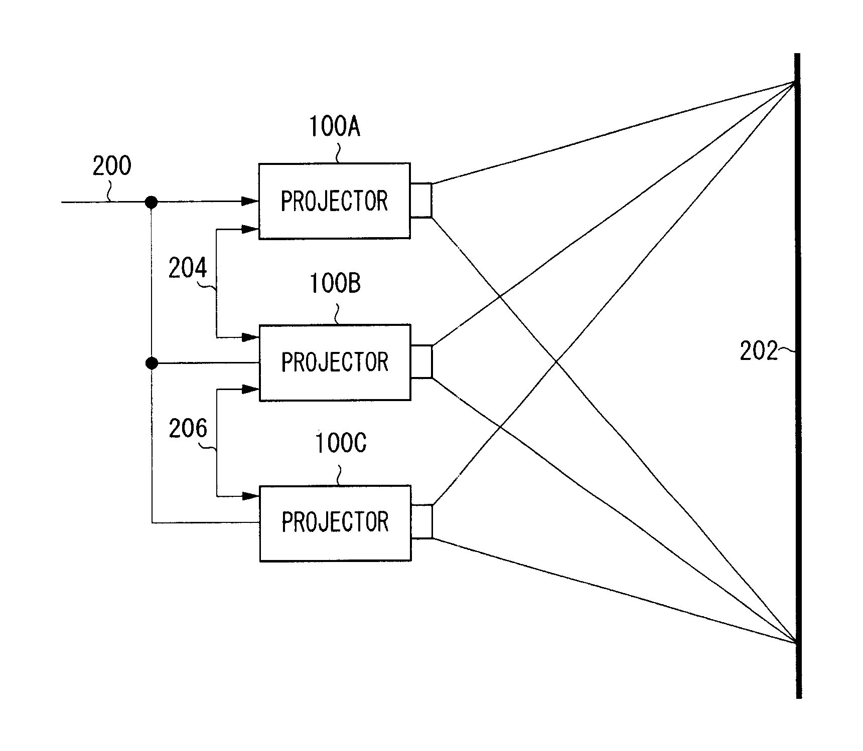
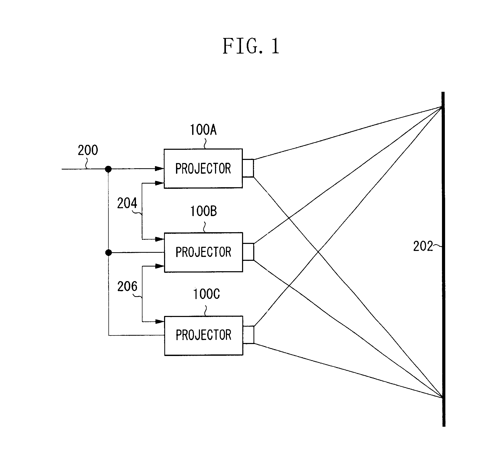
[0023]FIG. 1 is a schematic block diagram illustrating a configuration of a first exemplary embodiment of a projection display system. Video signals are supplied from a video signal source (not shown) to three projectors 100A through 100C via a video cable 200. The three projectors 100A through 100C project images on the same region on a screen 202. The projectors 100A through 100C can communicate with one another via communication cables 204 and 206 to exchange information concerning operating-conditions of the projectors 100A through 100C, control signals and image data. Wireless communication can be used instead of the communication cables 204 and 206.

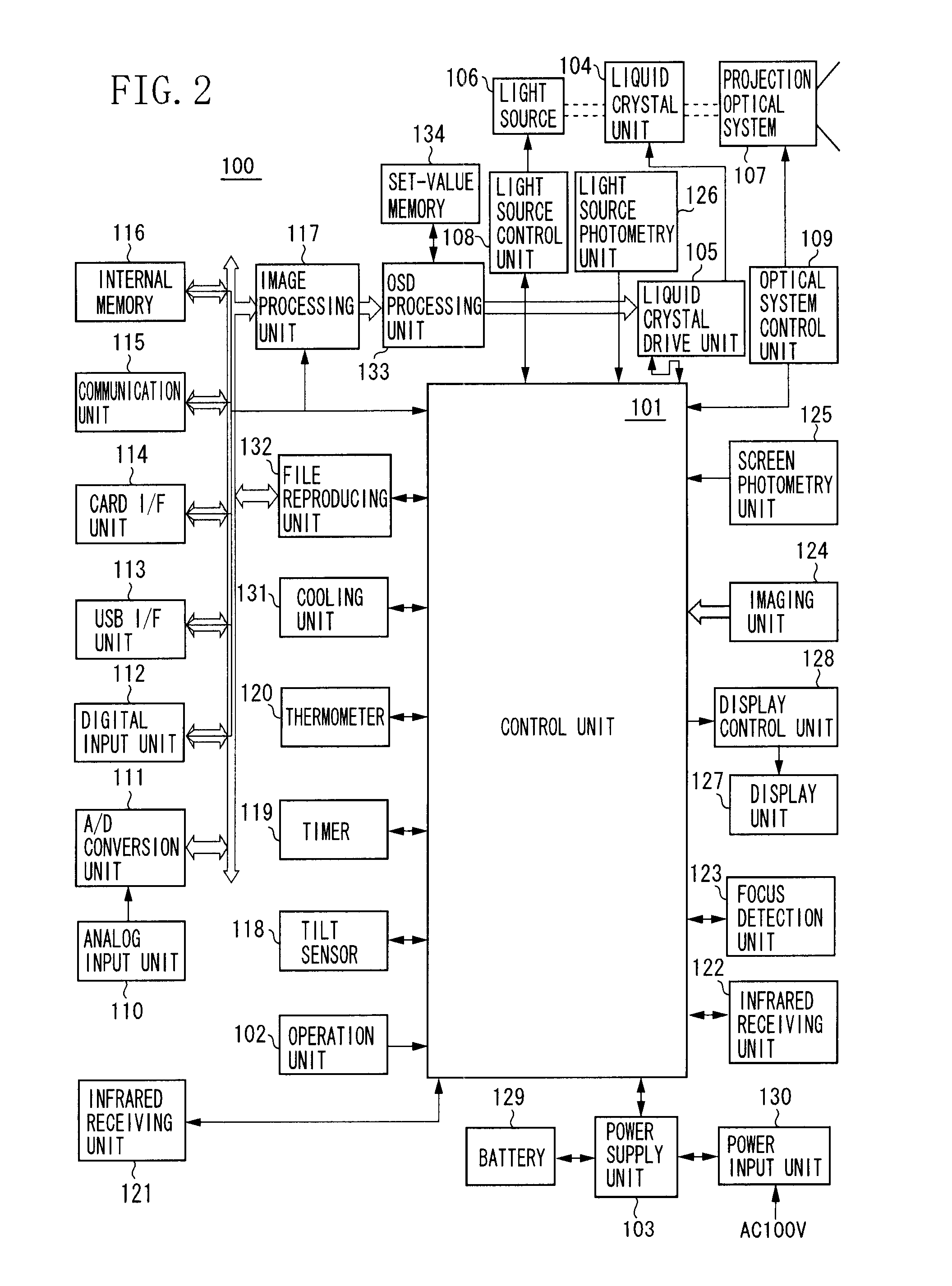
[0024]Each of the projectors 100A through 100C is configured with a projector 100 of the same configuration. FIG. 2 is a schematic block diagram illustrating the projector 100. A control unit 1...


PUM


Abstract

A projection apparatus includes a communication unit, an obtaining unit, a projection unit, a generator, and a controller. The communication unit communicates with an other projection apparatus. The obtaining unit obtains image data and the projection unit projects an image based on the image data obtained by the obtaining unit. The generator generates an on-screen-display (OSD) image. The controller controls the projection unit to project a projection image by superimposing the OSD image onto an image, based on the image data obtained by the obtaining unit, in a stack projection mode in which a projection image of the projection unit and a projection image of the other projection apparatus are projected to be superimposed with each other, and to transmit, to the other projection apparatus, information concerning a position at which the OSD image is superimposed.

Description

BACKGROUND OF THE INVENTION[0001]1. Field of the Invention[0002]The present invention relates to a projection system.[0003]2. Description of the Related Art[0004]Hitherto, a projection apparatus, i.e., a projector for projecting an image on a screen has widely been commercialized. In addition, a projection system has been known, which displays projection images respectively projected from a plurality of projection apparatuses onto the same position by superimposing the projection images thereonto, for purposes of enhancing luminance of each of the projection images and stereoscopically displaying the projection images utilizing parallax. Many projectors have an on-screen-display (OSD) function of displaying a menu screen on the projection image with a view to displaying or adjusting operating-conditions.[0005]If projection images are projected by a plurality of projectors onto the same projection plane, when a certain projector projects an image including an OSD screen, a projection...

Claims


Application Information

Patent Timeline
Patent Type & Authority Applications(United States)
IPC IPC(8): G09G5/00
CPCH04N9/3179H04N9/3197G06F3/1446G09G2320/0606G09G2320/08G09G2340/0464G09G5/377G09G2370/06H04N5/44504H04N9/3147H04N21/4122H04N21/4854H04N1/00249G09G2340/12
Inventor OKA, NOBUHIRO
Owner CANON KK
Why Eureka
Try Eureka