Liquid discharging apparatus and liquid discharging method

a liquid discharging apparatus and liquid discharging technology, applied in the direction of matrix printers, visual presentations, instruments, etc., can solve the problem of image quality reduction, and achieve the effect of suppressing the quality of an overall image and reducing the effect of image quality

Active Publication Date: 2020-06-09
SEIKO EPSON CORP
View PDF10 Cites 0 Cited by
  • Summary
  • Abstract
  • Description
  • Claims
  • Application Information

AI Technical Summary

Benefits of technology

[0006]According to the application example, in a case in which a non-discharging nozzle occurs, supplementing printing data is generated for nozzles of the same nozzle group to which the non-discharging nozzle belongs, and the printing process is carried out on the basis of the supplementing printing data. As a result of this, it is possible to supplement a deficit in an image that occurs due to the non-discharging nozzle. Further, in this case, a non-discharging nozzle and a supplementing nozzle are nozzles within the same nozzle group. Accordingly, effects such as attachment error (alignment error) of the nozzle group are reduced, and therefore, variation in a landing position of the liquid with respect to the medium is suppressed, and it is possible to prevent deterioration in image quality. Additionally, for example, the term non-discharging nozzle refers to a nozzle in a state in which the liquid is not being discharged from a nozzle as a result of a contaminant being attached to the nozzle or an air bubble being incorporated in the nozzle.Application Example 2
[0023]According to the application example, even in a case in which the occurrence number of non-discharging nozzle in a predetermined nozzle group is comparatively high, the printing Duty is supplemented with other nozzle groups in a case in which the possible printing Duty on a predetermined nozzle group is smaller than the set printing Duty. As a result of this, effects on the image are reduced, and therefore, it is possible to suppress deterioration in the quality of an overall image.

Problems solved by technology

However, in the above-mentioned apparatus, for example, in a case of supplementing with a nozzle of a head other than a head to which a non-discharging nozzle belongs, there is a problem in that a landing position of supplemented ink deviates due to an attachment error between the heads, or the like, and therefore, the image quality is reduced.

Method used


Image

  • Liquid discharging apparatus and liquid discharging method
  • Liquid discharging apparatus and liquid discharging method
  • Liquid discharging apparatus and liquid discharging method

Examples


first embodiment

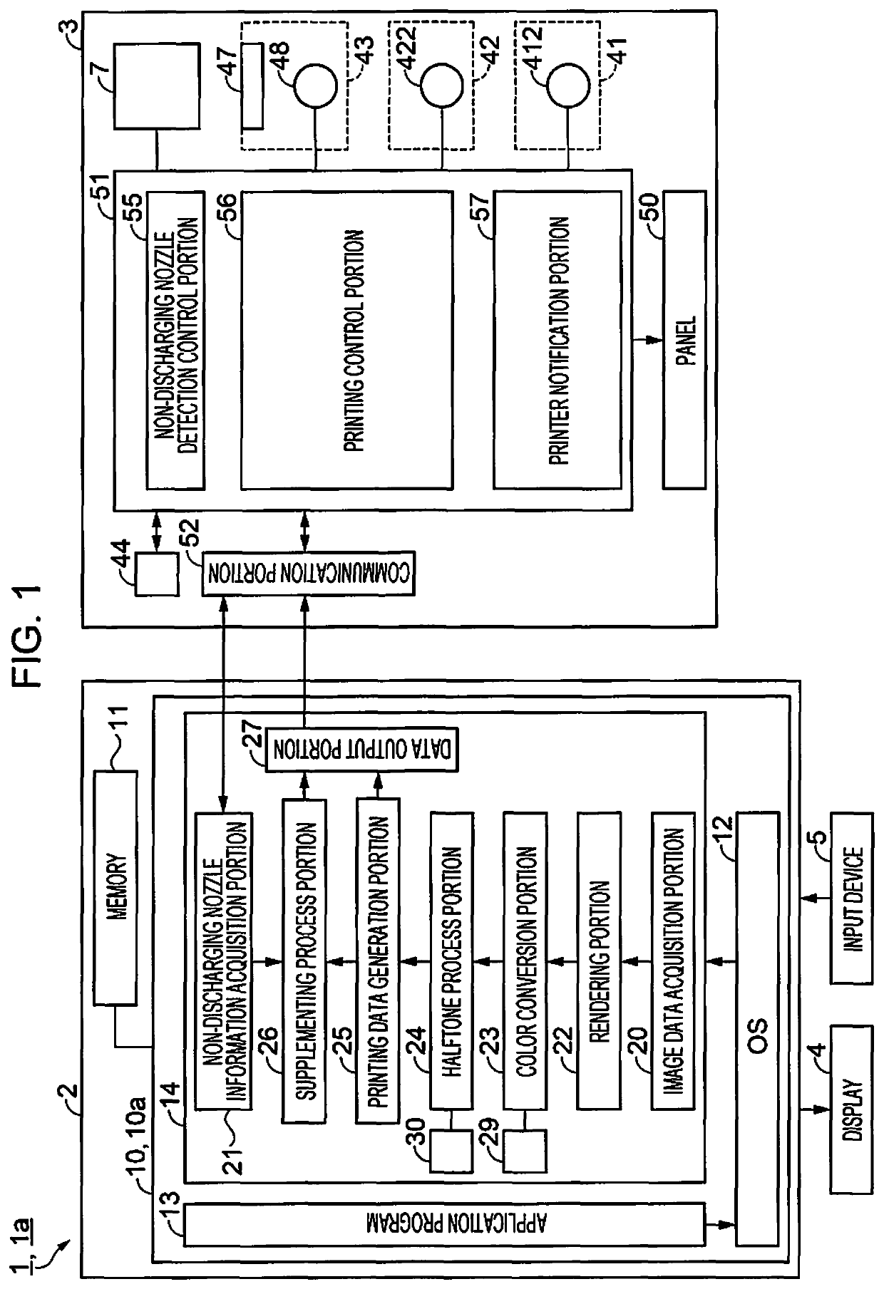
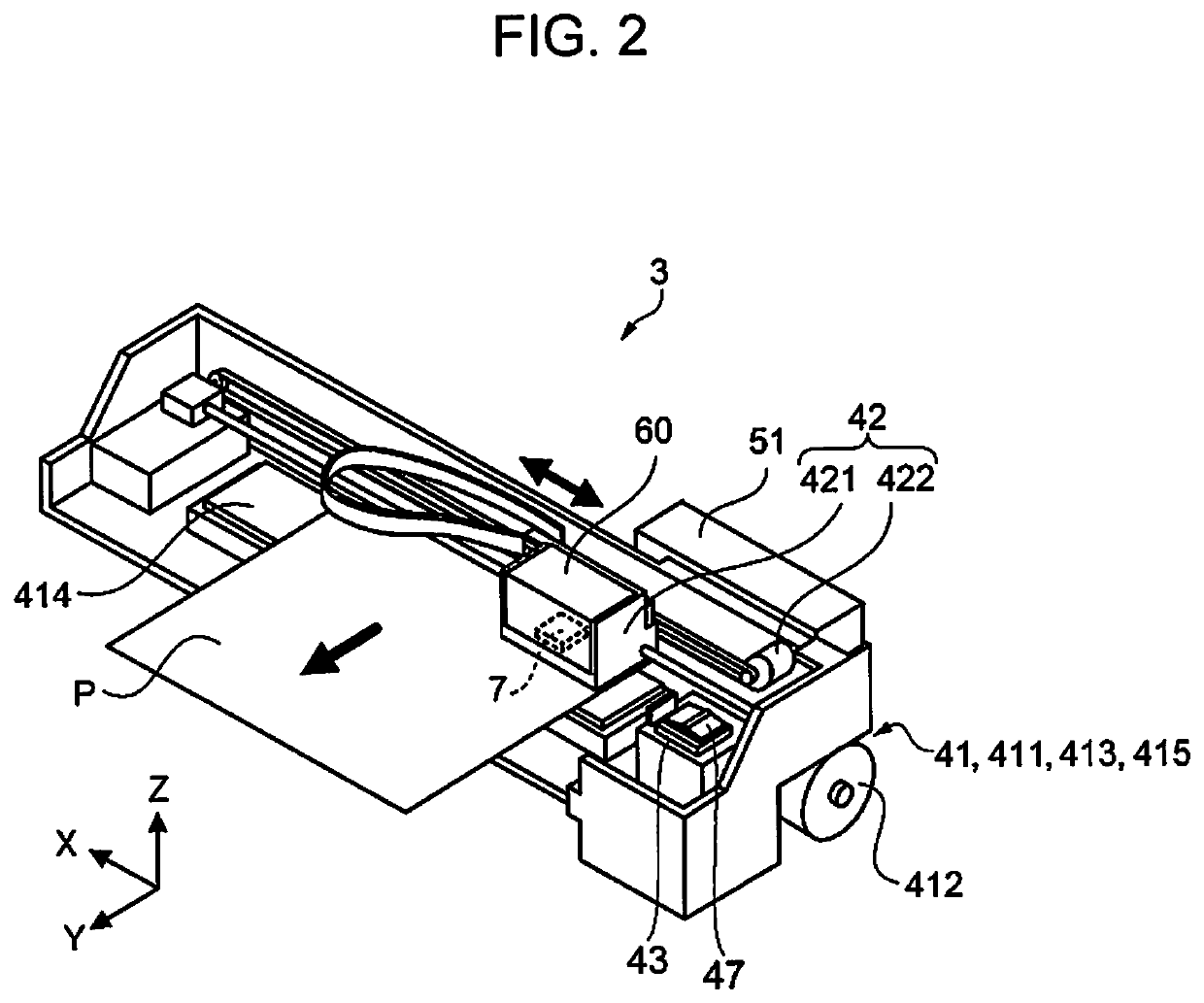
[0041]Firstly, a configuration of a liquid discharging apparatus will be described. A liquid discharging apparatus is an apparatus provided with a head including a plurality of nozzles that are capable of discharging a liquid onto a medium, a main scanning portion that scans the head in a main scanning direction, a sub-scanning portion that relatively moves the head and the medium in a sub-scanning direction, which intersects the main scanning direction, and a control portion. FIG. 1 is a block diagram that shows a configuration of a liquid discharging apparatus, and FIG. 2 is a perspective view that shows a configuration of a printer.

[0042]As shown in FIG. 1, a liquid discharging apparatus 1 is a printing system that is provided with a computer 2 and a printer 3. A display 4, and an input device 5 such as a keyboard or a mouse are connected to the computer 2. The printer 3 is provided with a head 7, discharges an ink, as a liquid, from the head 7 as ink droplets, and is configured ...

second embodiment

[0101]Next, a second embodiment will be described. More specifically, in the first embodiment, a nozzle within the same nozzle group as a non-discharging nozzle is set as a supplementing nozzle, but in the present embodiment, a supplementing process method of a case in which it is not possible to select a supplementing nozzle using a nozzle within the same nozzle group as a non-discharging nozzle, will be described. Additionally, the basic configuration of the liquid discharging apparatus 1 is similar to that of the first embodiment, and therefore, description thereof will be omitted, and a section that differs from the first embodiment, that is, a liquid discharging method will be described.

[0102]The liquid discharging method of the present embodiment is a method that generates supplementing printing data, which corrects printing data in a manner in which it is possible to supplement with a plurality of nozzles within another nozzle group that differs from the predetermined nozzle ...

third embodiment

[0111]Next, a third embodiment will be described. Additionally, the basic configuration and the printing format of a liquid discharging apparatus of the present embodiment are similar to those of the first embodiment, and therefore, description thereof (refer to FIGS. 1 to 6) will be omitted, and a section that differs from the first embodiment, that is, the configuration of a control portion will be described. FIGS. 11 to 14 are explanatory views that show configurations of a control portion.

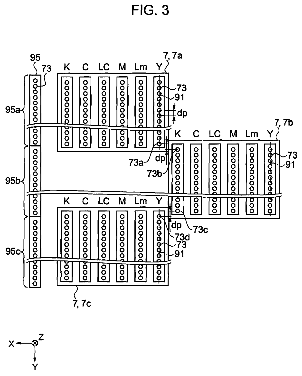
[0112]A control portion 10a of a liquid discharging apparatus 1a of the present embodiment acquires a possible printing Duty of a predetermined band region (a predetermined nozzle group) on the basis of a number of occurrences of non-discharging nozzles in the predetermined band region (the first to third band regions Ba1, Ba2, and Ba3 (refer to FIG. 6)) that corresponds to the predetermined nozzle group (for example, the first to third nozzle groups 95a, 95b, and 95c (refer to FIGS. 3 and 5)),...


PUM


Abstract

A liquid discharging apparatus is provided with a head including a plurality of nozzle groups, a main scanning portion that scans the head in a main scanning direction, a sub-scanning portion that relatively moves the head and the medium in a sub-scanning direction, which intersects the main scanning direction, and a control portion, in which the control portion generates supplementing printing data, which corrects printing data in a manner in which it is possible to supplement with another nozzle within a predetermined nozzle group and executes a printing process on the basis of the supplementing printing data in a case in which it is determined that a predetermined nozzle within the predetermined nozzle group is a non-discharging nozzle when forming a plurality of raster lines on the medium by discharging the liquid from the nozzles of the plurality of nozzle groups.

Description

BACKGROUND1. Technical Field[0001]The present invention relates to a liquid discharging apparatus and liquid discharging method.2. Related Art[0002]In the related art, an ink jet recording apparatus that is provided with a plurality of heads, and that supplements a non-discharging nozzle with another nozzle in multi-pass character printing using the plurality of heads, is known (for example, refer to JP-A-2005-246840).[0003]However, in the above-mentioned apparatus, for example, in a case of supplementing with a nozzle of a head other than a head to which a non-discharging nozzle belongs, there is a problem in that a landing position of supplemented ink deviates due to an attachment error between the heads, or the like, and therefore, the image quality is reduced.SUMMARY[0004]The invention can be realized as the following aspects or application examples.Application Example 1[0005]According to this application example, there is provided a liquid discharging apparatus including a head...

Claims


Application Information

Patent Timeline
Patent Type & Authority Patents(United States)
IPC IPC(8): B41J2/21G06K15/10B41J2/045
CPCG06K15/105B41J2/2139B41J2/2132B41J2/04543B41J2/2142
Inventor YOSHIKAWA, EISHIN
Owner SEIKO EPSON CORP
Why Eureka
Try Eureka