Vulcanizing system

a vulcanizing system and raw tire technology, applied in the direction of tyres, belts, domestic applications, etc., can solve the problems of large energy loss and large loss of heat of steam, and achieve the effect of reducing the heat dissipation of the piping, preventing the progress of vulcanization, and reducing the length of the piping

Inactive Publication Date: 2013-09-10
MITSUBISHI HEAVY IND LTD
View PDF10 Cites 2 Cited by
  • Summary
  • Abstract
  • Description
  • Claims
  • Application Information

AI Technical Summary

Benefits of technology

[0050]According to the distributed-type vulcanizing system of the present invention, a piping length from the boilers to the vulcanizers can be shortened, and therefore heat dissipation from the piping can be significantly decreased. Also, in the distributed-type vulcanizing system of the present invention, even when a small-sized boiler is used, the temperature and the pressure can be boosted by the temperature booster and the pressure booster to supply steam to the vulcanizers belonging to the group, thereby allowing vulcanization of the raw tire without any trouble.
[0051]Furthermore, according to the tire vulcanizing method of the present invention, in the temperature-boosting process, when the temperature of the condensed water is low due to a low temperature of the saturated steam, which may possibly hinder the progress of vulcanization, the saturated steam is heated to generate overheated steam. With this, it is possible to supplement the lack of capabilities of the small-sized boiler and cause vulcanization to smoothly proceed.

Problems solved by technology

In the structure as described above, however, when steam is supplied from the boiler 102 to via the piping 103 to each vulcanizer 101, a considerable amount of heat of steam is lost by heat dissipation from the piping 103, thereby causing a large energy loss.

Method used


Image

  • Vulcanizing system
  • Vulcanizing system
  • Vulcanizing system

Examples


first embodiment

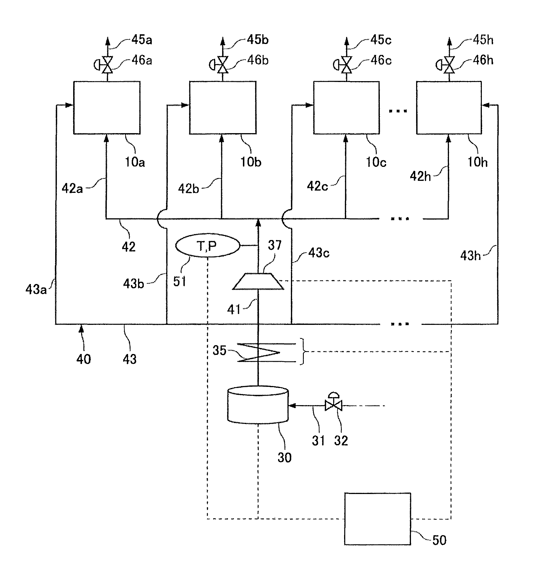
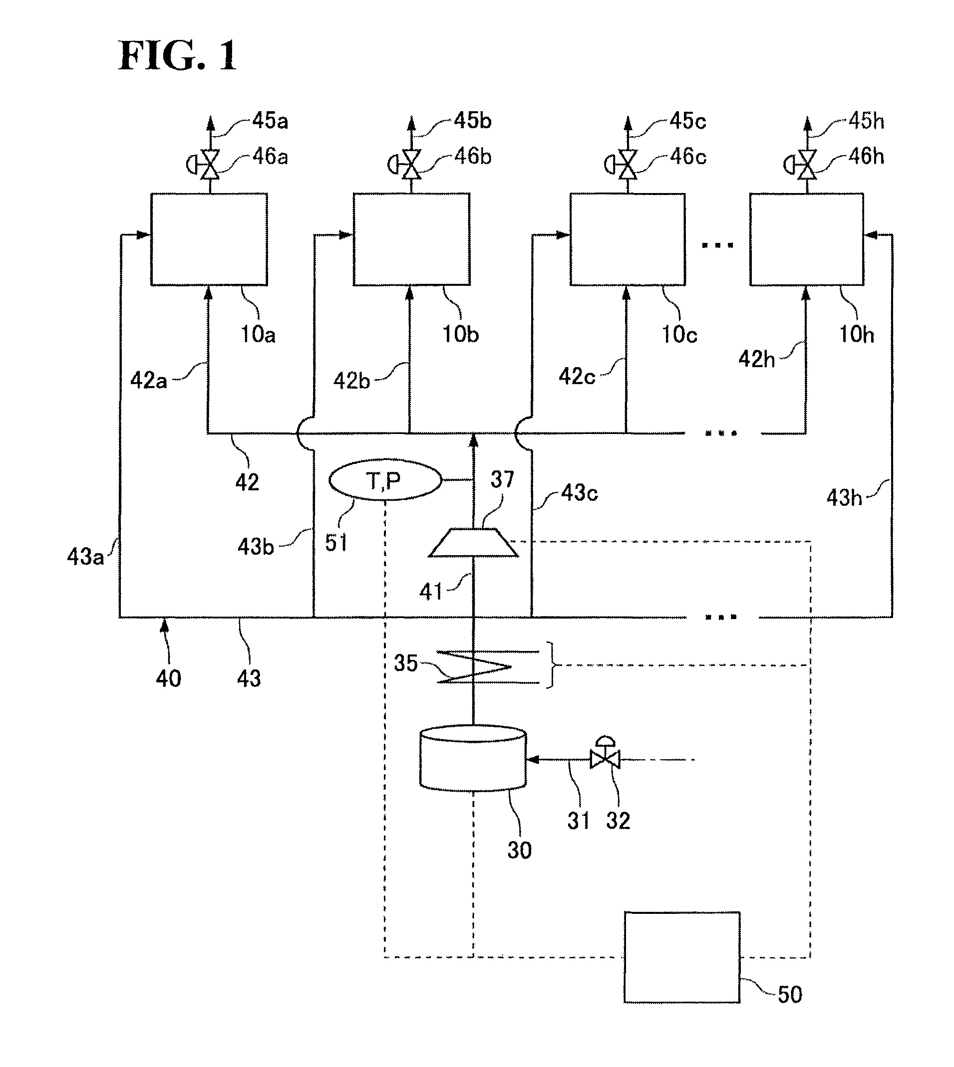
[0071]As shown in FIG. 1, the groups Gr-1 to Gr-n each include six to ten vulcanizers 10a to 10h. To the vulcanizers 10a to 10h, steam is supplied from the boiler 30. To the boiler 30, a water supply path 31 for supplying water to the boiler 3 from a supply source not shown is connected, and an amount of water adjusted by a valve 32 provided on the water supply path 31 is supplied to the boiler 30. The boiler 30 and the vulcanizers 10a to 10h are connected via the steam supply path 40 through which steam generated in the boiler 30 passes. On the steam supply path 40, a temperature booster 35 and a pressure booster 37 are provided. The temperature booster 35 and the pressure booster 37 boost the temperature and pressure of the steam generated in the boiler 30. These increases in temperature and pressure is to make the temperature and pressure to those required for vulcanization of a raw tire. The same goes for the following. Also, to the steam supply path 40, a sensor 51 detecting a ...

second embodiment

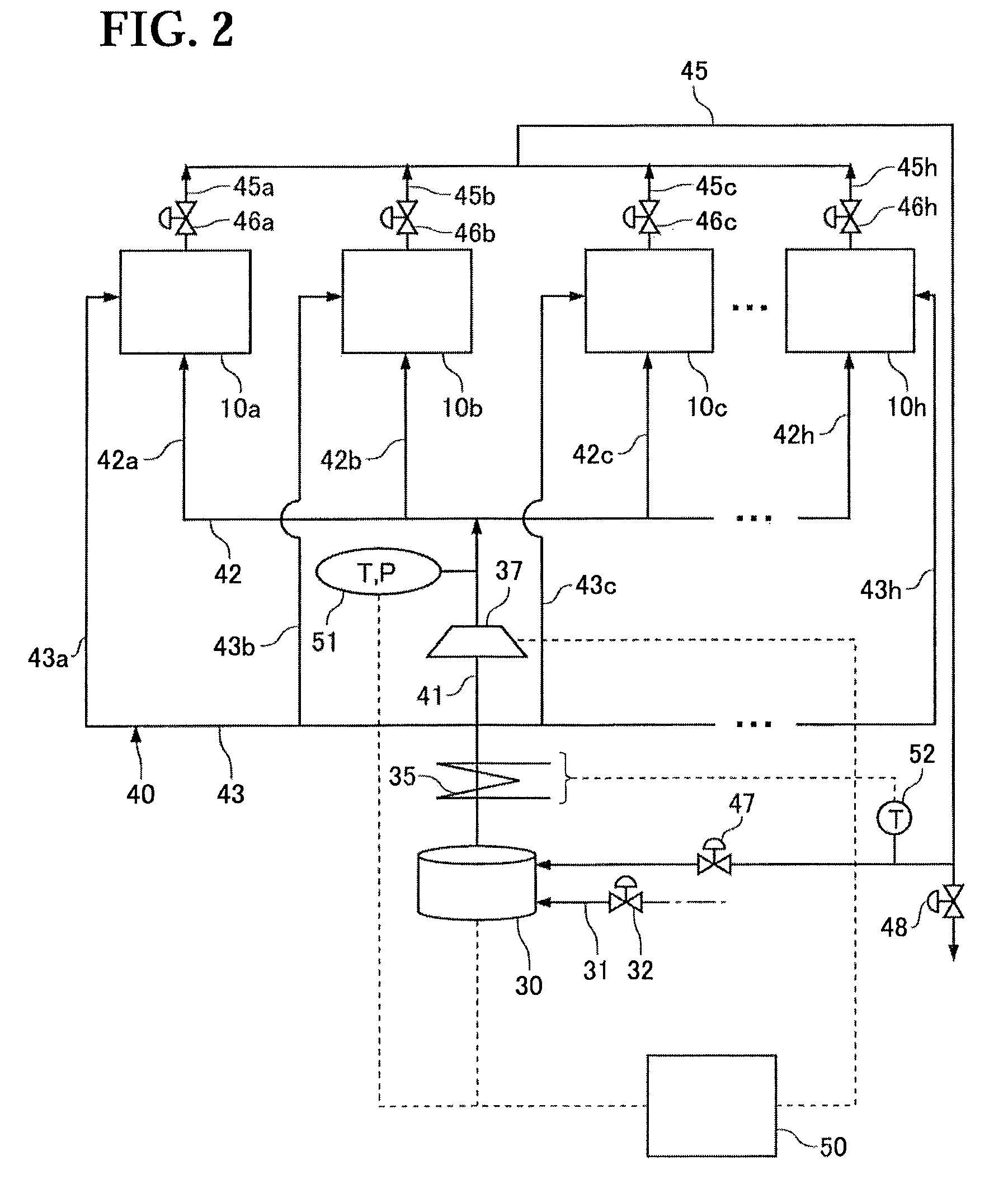
[0102]A second embodiment according to the present invention is described based on FIG. 2. Note that components identical to those in the first embodiment are provided with the same reference character as that of FIG. 1 and are not described herein.

[0103]In the second embodiment, discharge piping 45a to 45h connected to the vulcanizers 10a to 10h, respectively, are collected to one end of a circular piping 45. The other end of the circular piping 45 is connected to the boiler 30. Also, the circular piping 45 includes a valve 48 for discharging a drain to the outside of the system.

[0104]A drain occurring in each of the vulcanizers 10a to 10h is returned to the boiler 30 via the circular piping 45. The drain to be returned to the boiler 30 has a temperature equal to or higher than 100° C. Therefore, if the drain is supplied to the boiler 30 in addition to water supplied from the water supply path 31, the operation capabilities of the boiler 30 for obtaining steam at a predetermine tem...

third embodiment

[0108]A third embodiment according to the present invention is described based on FIG. 3. Note that components identical to those in the first and second embodiments are provided with the same reference character as that of FIG. 1 and FIG. 2 and are not described herein.

[0109]In the third embodiment, the discharge pipings 45a to 45h connected to the vulcanizers 10a to 10h, respectively, are collected to one end of a circular piping 53. The other end of the circular piping 53 is connected to the main supply path 41. That is, the third embodiment is different from the second embodiment in the destination to which a drain is returned.

[0110]The circular piping 53 is provided with a temperature booster 54. A drain flowing through the circular piping 53 can be temperature-boosted by the temperature booster 54 to become steam. This steam is supplied to the main supply path 41, and is further temperature-boosted by the temperature booster 35 provided on the main supply path 41. A part of th...


PUM

PropertyMeasurementUnit
total lengthaaaaaaaaaa
temperatureaaaaaaaaaa

Abstract

In a vulcanizing system of the present invention, a temperature booster and a pressure booster are provided on a steam supply path connecting vulcanizers that belong to groups and a boiler allocated to the groups. The temperature booster and the pressure booster are sequentially arranged from an upstream side, a second branch supply path for supplying the steam to a mold between the temperature booster and the pressure booster is branched from the steam supply path. The second branch supply path is preferably in a form of allowing the steam temperature-boosted by the temperature booster to be supplied to the mold by bypassing the pressure booster.

Description

RELATED APPLICATIONS[0001]The present application is a National Phase of International Application Number PCT / JP2011 / 001679 filed Mar. 22, 2011, and claims priority from, Japanese Application Number 2010-183925 filed Aug. 19, 2010.TECHNICAL FIELD[0002]The present invention relates to a method of vulcanizing a raw tire and its system.BACKGROUND ART[0003]Normally, to vulcanize a raw tire, a mold (a metal mold) having its inside filled with a raw tire is heated by a heating medium, and a heating medium including high-temperature, high-heat-capacity steam and a pressurizing medium including noncondensable gas such as inert gas or nitrogen gas are supplied to an internal space of the raw tire, thereby heating the raw tire from outside and inside (for example, refer to Patent Document 1). Note that the heating medium and the pressurizing medium may be hereinafter collectively referred to as a vulcanization medium.[0004]In general, as shown in FIG. 15, a vulcanizing system 300 includes a b...

Claims


Application Information

Patent Timeline
Patent Type & Authority Patents(United States)
IPC IPC(8): B29C33/04
CPCB29C33/04B29D30/0601B29C35/049B29D2030/0675B29D2030/067B29C35/04B29L2030/00
Inventor TANAKA, KAZUNARIMATSUDA, NAOHIKOYOKO, KAZUTOSHIFUKUDA, HIDEKISHINTANI, KOJITOMOTO, KEIICHI
Owner MITSUBISHI HEAVY IND LTD
Why Eureka
Try Eureka