
Payment system and method

a payment system and payment method technology, applied in the field of payment systems and methods, can solve problems such as systems and methods

Active Publication Date: 2020-06-23
SKALA THOMAS
View PDF119 Cites 0 Cited by
  • Summary
  • Abstract
  • Description
  • Claims
  • Application Information

AI Technical Summary

Problems solved by technology

The payment systems and methods heretofore known suffer from a number of disadvantages as described herein and which one of ordinary skill in the art would be aware of and / or would become aware of upon reading the disclosure found herein.

Method used


Image

  • Payment system and method
  • Payment system and method
  • Payment system and method

Examples


Embodiment Construction

[0019]For the purposes of promoting an understanding of the principles of the invention, reference will now be made to the exemplary embodiments illustrated in the drawing(s), and specific language will be used to describe the same. It will nevertheless be understood that no limitation of the scope of the invention is thereby intended. Any alterations and further modifications of the inventive features illustrated herein, and any additional applications of the principles of the invention as illustrated herein, which would occur to one skilled in the relevant art and having possession of this disclosure, are to be considered within the scope of the invention.

[0020]Many of the functional units described in this specification have been labeled as modules in order to more particularly emphasize their implementation independence. For example, a module may be implemented as a hardware circuit comprising custom VLSI circuits or gate arrays, off-the-shelf semiconductors such as logic chips,...


PUM


Abstract

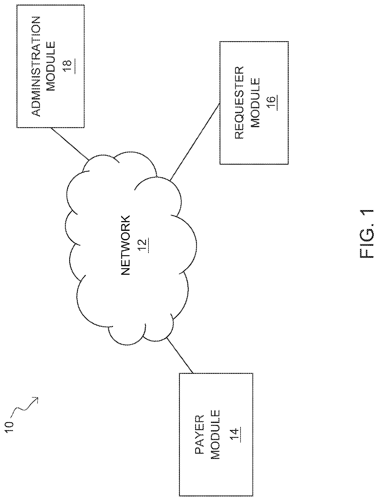
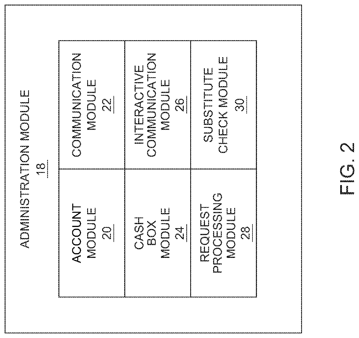
A payment system having a payer module and a requester module functionally coupled over a network and managed by an administration module that produces electronic substitute checks in response to instructions from the payer module. The payment system includes a risk management module that performs a risk management operation before the system produces an electronic substitute check.

Description

CROSS-REFERENCE TO RELATED APPLICATIONS[0001]This invention claims priority, under 35 U.S.C. § 120, to the U.S. Provisional Patent Application No. 62 / 046,837 to Thomas Skala filed on Sep. 5, 2014, which is incorporated by reference herein.BACKGROUND OF THE INVENTION[0002]Field of the Invention[0003]The present invention relates to payment systems and methods, specifically a push-style payment system and method.[0004]Description of the Related Art[0005]Traditional methods for moving payments electronically from a consumer or borrower to a merchant or lender have been carried out under what is described as a “pull” or “grab” model. In this method of transaction handling, the payer gives to the merchant some set of identifying information (credit card number, bank account routing numbers, etc.) along with some form of “authorization” statement. The merchant or lender then uses that information to submit a transaction against the payer's account to “grab” or “pull” the funds.[0006]The p...

Claims


Application Information

Patent Timeline
Patent Type & Authority Patents(United States)
IPC IPC(8): G06Q40/00G06Q20/04G06Q20/40G06Q20/00
CPCG06Q20/4016G06Q40/125G06Q20/0425
Inventor SKALA, THOMAS
Owner SKALA THOMAS
Learn More