Mobile phone with an eye illumination

a mobile phone and eye illumination technology, applied in the field of portable devices, can solve the problems of increased panel thickness, complicated manufacture, and intransparency, and achieve the effects of improving video image, local brightening, and minimizing shielding

Active Publication Date: 2020-06-23
ZEPPELIN CORP
View PDF3 Cites 0 Cited by
  • Summary
  • Abstract
  • Description
  • Claims
  • Application Information

AI Technical Summary

Benefits of technology

[0008]A device comprises a control unit; a memory coupled to the control unit to store data; a substantially transparent panel to minimizes EM shielding effect, wherein the substantially transparent panel includes a first substrate having a transparent electrode coupled to the control unit, a stacked gate formed over the first substrate and emitters formed adjacent to the stacked gate, a second substrate having fluorescent substances spaced apart from the first substrate, wherein the fluorescent substances emits green, blue or red light while electrons emitted by the emitter contact to the fluorescent substances. The portable device further comprises an antenna located corresponding to the substantially transparent panel to minimize the EM shielding effect, thereby improving signal receiving / transmitting performance. Alternatively, the portable device comprises at least one transparent antenna attached on the substantially transparent panel to minimize the EM shielding effect.

Problems solved by technology

Furthermore, the conventional LCD display has a lot of drawbacks, for example, the LCD display needs back light module which increases the thickness of the panel and it is not transparent.
Moreover, the device requires large arrays of thin film transistors, the manufacture is complicated and the resolution is not enough.
The mouse is inconvenient to a user, especially, to a portable device.
But the goal of size reduction is frustrated by the present of the elements mentioned above.

Method used


Image

  • Mobile phone with an eye illumination
  • Mobile phone with an eye illumination
  • Mobile phone with an eye illumination

Examples


Embodiment Construction

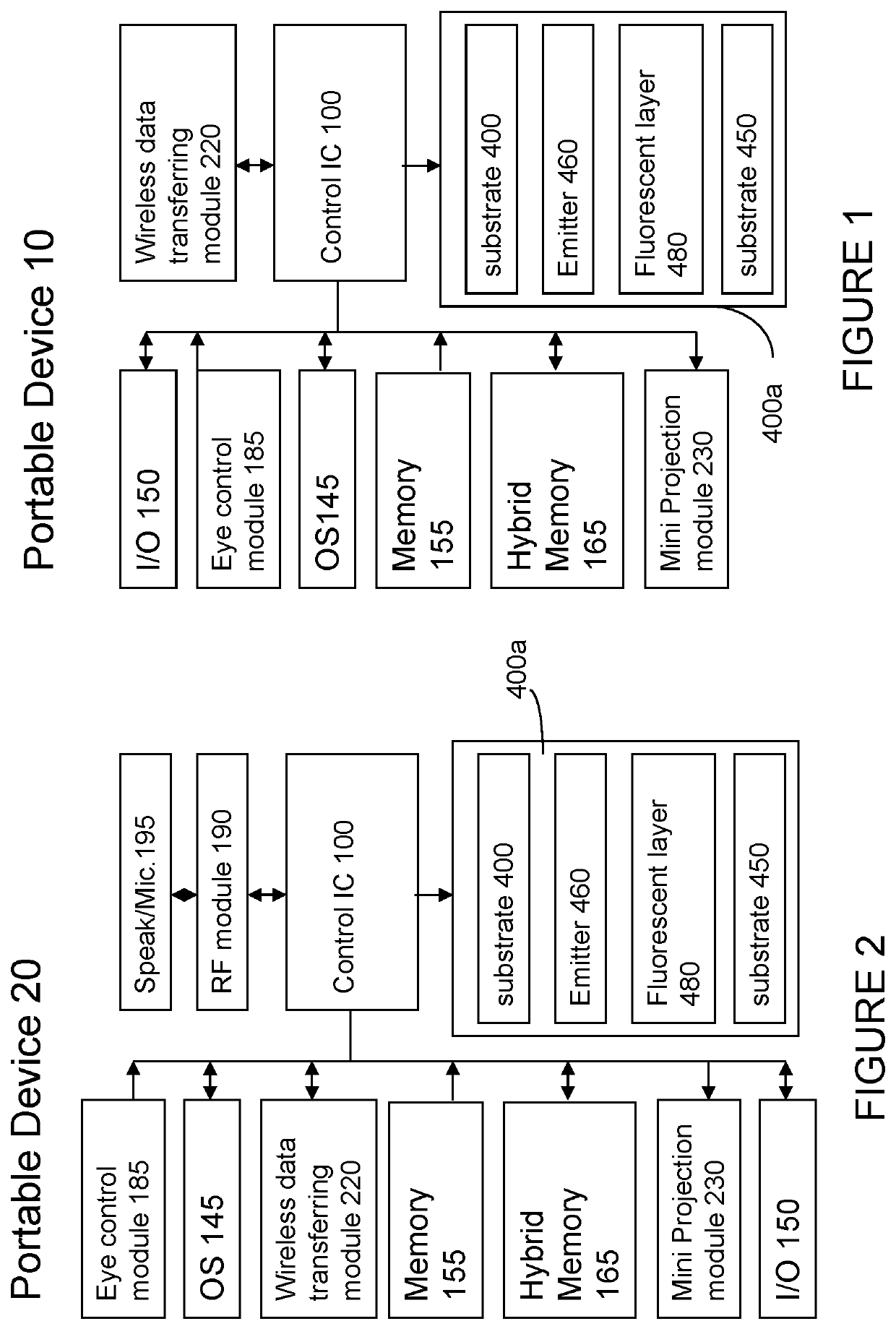
[0022]The present invention relates generally to a computing or portable device. The device includes but not limited to cellular phone, PDA (personal digital assistant), smart phone, notebook, digital still camera, digital video camera, medium player (MP3, MP4), GPS and the equivalent thereof.

[0023]FIG. 1 is a diagram illustrating main components of a portable communication device using a panel with emitters and a transparent substrate according to an embodiment of the present invention. In this embodiment, as shown in FIG. 1 and FIG. 2, the device 20 includes a RF module 190. As known in the art, the RF module 190 includes an antenna. This antenna is connected to a transceiver, which is used to receive and transmit signal. As known in the art, the RF module 190 further includes a CODEC, a DSP and an A / D converter as well. The RF module is not the feature of the present invention, and therefore, the detailed description is omitted. Other major components in a device 10 and 20 are si...


PUM

PropertyMeasurementUnit
conductiveaaaaaaaaaa
transmission priorityaaaaaaaaaa
signal strengthaaaaaaaaaa

Abstract

A mobile phone includes a control unit, a first wireless module coupled to the control unit, a second wireless module coupled to the control unit, a first transparent substrate having a first conductive line and a second transparent substrate having a second conductive line, fluorescent substances are formed between the first transparent substrate and the second transparent substrate, wherein a bias is applied to excite the fluorescent substances by combination of an electron and a hole to emit visible light, thereby removing backlight of the mobile phone. An antenna is disposed at side of the first transparent substrate to improve receiving or transmission. An eye illumination source is coupled to the control unit to measure an eye of a subject before the mobile phone, at least one CMOS sensor coupled to the control unit to sense an eye illumination from the eye of the subject.

Description

CROSS-REFERENCE TO RELATED APPLICATIONS[0001]The application is a continuation application of U.S. patent application Ser. No. 13 / 612,854, filed on 13 Sep. 2012, now pending, which is a continuation application of U.S. patent application Ser. No. 11 / 724,262, filed on 15 Mar. 2007, now abandoned, which is a continuation-in-part application of U.S. patent application Ser. No. 11 / 011,465, filed on 13 Dec. 2004, now abandoned, the disclosure of which are hereby incorporated by reference herein in their entirety.TECHNICAL FIELD[0002]The present invention relates generally to a portable device, and more particularly to a mobile phone with an eye illumination.BACKGROUND OF RELATED ARTS[0003]Cellular communications systems typically include multiple base stations for communicating with mobile stations in various geographical transmission areas. Each base station provides an interface between the mobile station and a telecommunications network. Mobile telephone systems are in use or being de...

Claims


Application Information

Patent Timeline
Patent Type & Authority Patents(United States)
IPC IPC(8): G06K9/00H04M1/725G06F3/01H04N5/374H04M1/724
CPCH04M1/72519G06F3/013H04N5/374H04M2250/12G06F3/041G06F1/1643G06F1/1686G06F1/1694G06F1/1637G06F2203/04103G06F1/1626G06F1/1698H04M2250/52H04M1/22G06F1/1656H04M1/724H04N23/611H04N25/76
Inventor CHIANG, KUO-CHING
Owner ZEPPELIN CORP
Why Eureka
Try Eureka