Supercharge Your Innovation With Domain-Expert AI Agents!

Device and method for controlling operation of power module composed of switches

a technology of power modules and switches, applied in the direction of electronic switching, pulse generators, pulse techniques, etc., to achieve the effect of increasing the overall cost and physical surface area of the power modul

Active Publication Date: 2020-07-07
MITSUBISHI ELECTRIC CORP
View PDF12 Cites 0 Cited by
  • Summary
  • Abstract
  • Description
  • Claims
  • Application Information

AI Technical Summary

Benefits of technology

[0006]However, regardless of the type of die used, i.e. diodes or voltage-driven switch, e.g. MOSFETs (Metal Oxide Semiconductor Field Effect Transistor), characteristics exist within the dies that limit the balanced sharing of the load current both statically and dynamically. The incremental addition of each parallel die does not result in full utilization of the die, and thus, more dies are needed in parallel to achieve a given current rating, thereby increasing the overall costs and physical surface area of the power module.
[0007]In addition to the electrical characteristics of the die, the physical placement of the dies within the power module also limits the reliability and utilization of the dies. One such example is the unequal thermal distribution within a module due to heating from neighbouring dies. Unless the design of the module allows for sufficient spacing between the dies, thereby increasing the physical size of the power module, the dies close to the center of the power module experience higher temperatures than the dies close to the periphery of the power module.

Problems solved by technology

Emerging devices technologies, such as SiC (Silicon Carbide) and GaN (Gallium Nitride) Transistors, are typically realized in high current density, small power dies due to limitations of yield and cost of wafer substrate.

Method used


Image

  • Device and method for controlling operation of power module composed of switches
  • Device and method for controlling operation of power module composed of switches
  • Device and method for controlling operation of power module composed of switches

Examples


Embodiment Construction

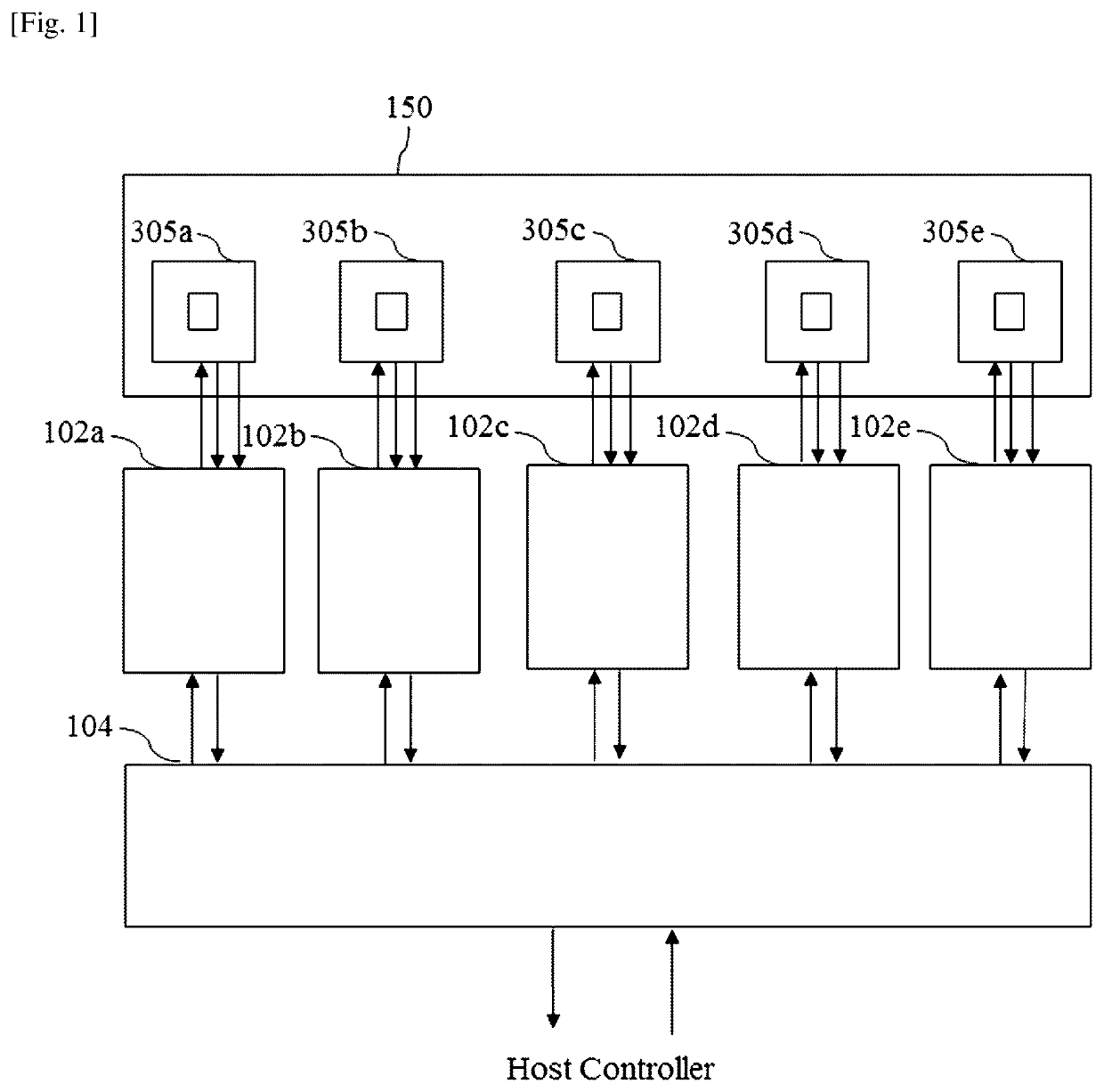
[0037]FIG. 1 represents an example of a system for controlling the operation of a multi-die power module according to the present invention.

[0038]The system for controlling the operation of the multi-die power module 150 uses power die feedback mechanisms like thermal information or on-state voltages or individual die voltage / current trajectory, to modulate the control electrode command for each individual die in the multi-die power module 150.

[0039]The system for controlling the operation of the multi-die power module 150 obtains, for each die, thermal information or on-state voltages or die voltage / current trajectory and controls each die according to the obtained information.

[0040]The system for controlling the operation of the multi-die power module 150 comprises a plurality of devices 102 for controlling the operation of a power die 305, one for each die.

[0041]In the example of FIG. 1, the system for controlling the operation of the multi-die power module 150 comprises five dev...


PUM


Abstract

The present invention concerns a device for controlling the operation of a power module composed of switches, each switch being composed of a plurality of power dies connected in parallel, characterized in that the device comprises, for each power die of the power module: —a temperature sensor to sense the temperature of the power die, —a current sensor to sense the current going through the power die, —a gate interrupt circuit to interrupt the signal provided to the power die if the sensed current is higher than a predetermined current threshold, —a controller to reduce the conducting time of the die if the sensed temperature of the power die is higher than the average die temperature across the power dies of at least one switch.

Description

TECHNICAL FIELD[0001]The present invention relates generally to a device for controlling the operation of a multi-die power module.BACKGROUND ART[0002]Multi-die power modules are classically composed of several parallel connected power dies and are used for increasing the current capability over that of a single power die.[0003]For example, a three-phase converter is composed of four parallel power dies per switch, giving twenty four power dies in total.[0004]Emerging devices technologies, such as SiC (Silicon Carbide) and GaN (Gallium Nitride) Transistors, are typically realized in high current density, small power dies due to limitations of yield and cost of wafer substrate.[0005]In order to realize higher power SiC-based modules, a multitude of parallel connected SiC dies is necessary. Unlike parallel connected modules, parallel connected dies constitute a single switch that ideally commutates the same load current.SUMMARY OF INVENTIONTechnical Problem[0006]However, regardless of...

Claims


Application Information

Patent Timeline
Patent Type & Authority Patents(United States)
IPC IPC(8): H02M1/32H03K17/082H03K3/011H01L25/07H02M1/08H02M1/00H03K17/14H03K17/12
CPCH03K17/145H03K3/011H03K17/0822H01L25/07H02M1/32H03K17/122H02M1/08H01L2924/0002H02M2001/0009H02M2001/327H01L2924/00H02M1/327H02M1/0009
Inventor EWANCHUK, JEFFREYMOLLOV, STEFAN
Owner MITSUBISHI ELECTRIC CORP
Features
  • R&D
  • Intellectual Property
  • Life Sciences
  • Materials
  • Tech Scout
  • Unparalleled Data Quality
  • Higher Quality Content
  • 60% Fewer Hallucinations
Learn More