Supercharge Your Innovation With Domain-Expert AI Agents!

System comprising multi-die power and method for controlling operation of multi-die power module

a power module and multi-die technology, applied in the direction of power conversion systems, pulse techniques, electronic switching, etc., can solve the problems and limiting the balanced sharing of load current statically and dynamically. the challenge of dynamic sharing only increased in severity, so as to achieve the effect of increasing the overall cost and physical surface area of the power modul

Inactive Publication Date: 2019-07-30
MITSUBISHI ELECTRIC CORP
View PDF3 Cites 0 Cited by
  • Summary
  • Abstract
  • Description
  • Claims
  • Application Information

AI Technical Summary

Benefits of technology

This approach enhances switching speed and maximum capability of multi-die power modules by minimizing oscillations and power losses, ensuring safe operation and extending the lifespan of the power module by adapting to current requirements and die capabilities without requiring highly dynamic control.

Problems solved by technology

However, regardless of the type of die used, i.e. diodes or voltage-driven switch, e.g. MOSFETs (Metal Oxide Semiconductor Field Effect Transistor), characteristics exist within the dies that limit the balanced sharing of the load current both statically and dynamically.
The incremental addition of each parallel die does not result in full utilization of the die, and thus, more dies are needed in parallel to achieve a given current rating, thereby increasing the overall costs and physical surface area of the power module.
Due to variations in the electrical characteristics of power devices during manufacturing, the currents are not equally shared across the dies and can be especially unbalanced during switching transitions.
Thus, as commutation speeds are increasing with newer technologies, such as SiC and GaN, this dynamic sharing challenge has only increased in severity.
As a result, the switching losses can significantly differ across parallel dies, leading to undesired temperature imbalance across dies, and eventually, early aging of the most stressed die.

Method used


Image

  • System comprising multi-die power and method for controlling operation of multi-die power module
  • System comprising multi-die power and method for controlling operation of multi-die power module
  • System comprising multi-die power and method for controlling operation of multi-die power module

Examples


Embodiment Construction

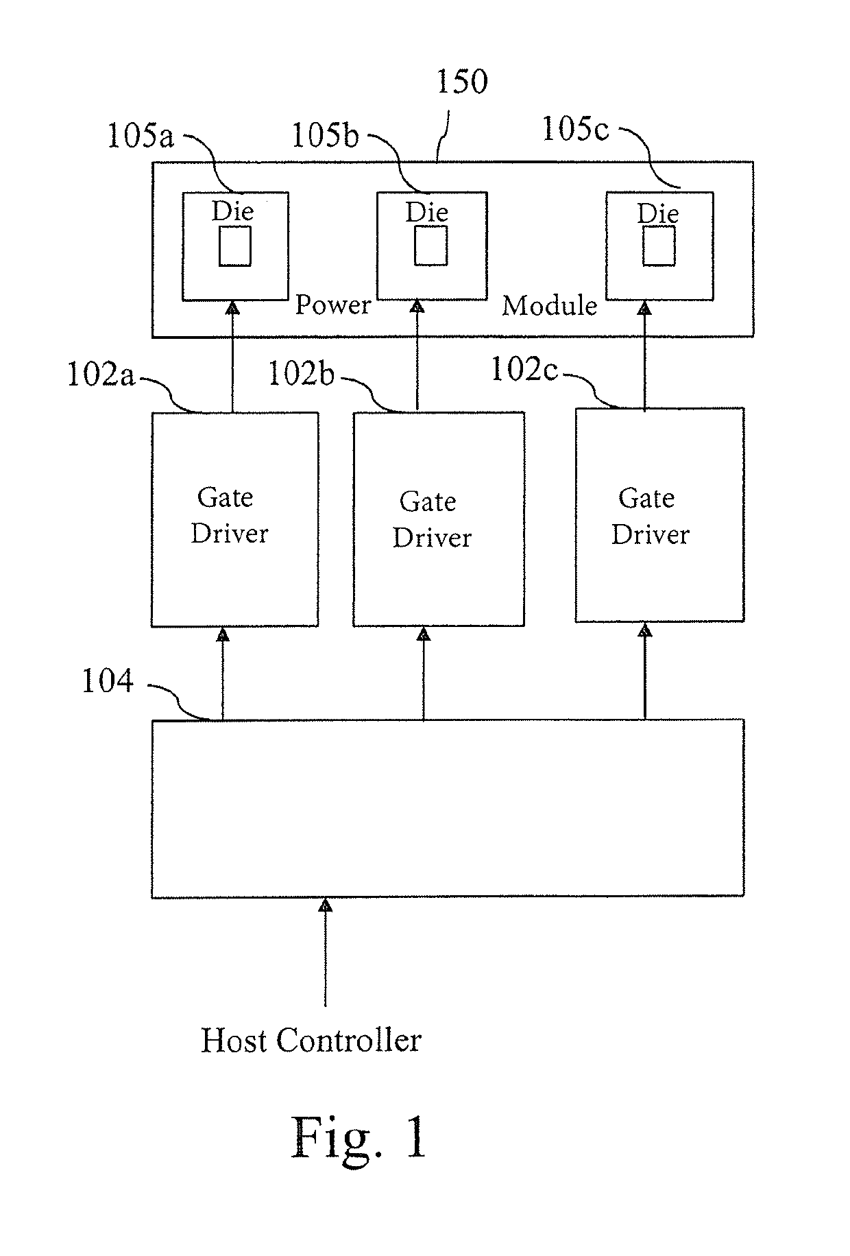
[0053]FIG. 1 represents an example of a system for controlling the operation of a multi-die power module according to the present invention.

[0054]The system for controlling the operation of the multi-die power module 150 uses an open loop mechanism and controls the switching time of the dies in the multi-die power module 150.

[0055]The system for controlling the operation of the multi-die power module 150 comprises a plurality of gate drivers 102 for providing a driving signal to at least one or plural dies 105 of the multi-die power module 150.

[0056]In the example of FIG. 1, the system for controlling the operation of the multi-die power module 150 comprises three gate drivers 102a to 102c for controlling the operation of three groups of at least one power die.

[0057]In the example of FIG. 1, each group of at least one power die comprises one die, respectively noted 105a to 105c.

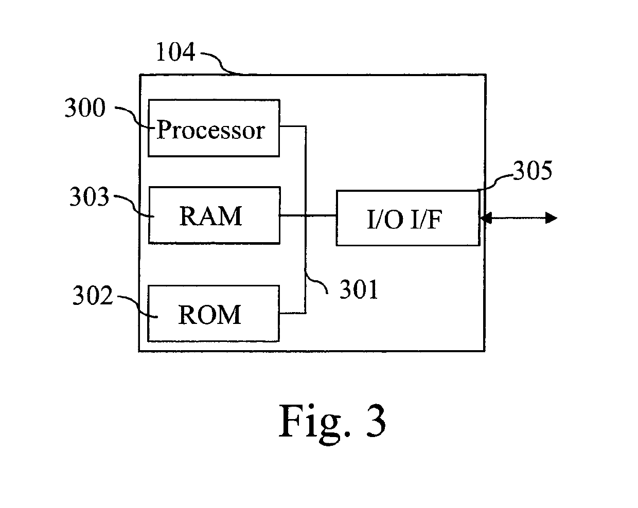
[0058]The gate drivers 102a to 102 receive command signal from a controller 104 which is disclosed in ref...


PUM


Abstract

The present invention concerns a system comprising a multi-die power module composed of dies and a controller receiving plural consecutive input patterns for activating the dies of the multi-die power module, wherein the dies are grouped into plural groups of at least one die and in that the controller comprises: —means for outputting one gate to source signal for each group of at least one die, the rising edges and / or falling edges of at least one gate to source signal being iteratively time shifted from the rising edge and / or a falling edge of the other gate to source signals for other groups of dies.

Description

TECHNICAL FIELD[0001]The present invention relates generally to a system and method for controlling the operation of a multi-die power module.BACKGROUND ART[0002]Multi-die power modules are classically composed of several parallel connected power dies and are used for increasing the current capability over that of a single power die.[0003]For example, a three-phase converter can be composed of four parallel power dies per switch, giving twenty four power dies in total.[0004]Emerging devices technologies, such as SiC (Silicon Carbide) and GaN (Gallium Nitride) Transistors, are typically realized in high current density, small power dies due to limitations of yield and cost of wafer substrate.[0005]In order to realize higher power SiC-based modules, a multitude of parallel connected SiC dies is necessary. Unlike parallel connected modules, parallel connected dies constitute a single switch that ideally commutates the same load current.SUMMARY OF INVENTION[0006]However, regardless of t...

Claims


Application Information

Patent Timeline
Patent Type & Authority Patents(United States)
IPC IPC(8): H02M1/088H03K17/14H03K17/12
CPCH03K17/14H03K17/145H03K17/122H02M1/088
Inventor MOLLOV, STEFANEWANCHUK, JEFFREY
Owner MITSUBISHI ELECTRIC CORP
Features
  • R&D
  • Intellectual Property
  • Life Sciences
  • Materials
  • Tech Scout
  • Unparalleled Data Quality
  • Higher Quality Content
  • 60% Fewer Hallucinations
Learn More