Supercharge Your Innovation With Domain-Expert AI Agents!

Method and device for controlling the operation of multi-die power module

Active Publication Date: 2019-06-25
MITSUBISHI ELECTRIC CORP
View PDF6 Cites 0 Cited by
  • Summary
  • Abstract
  • Description
  • Claims
  • Application Information

AI Technical Summary

Benefits of technology

The patent text discusses the problem of temperature differences in a power module made up of multiple dies. These temperature differences result in reduced performance and require more dies to be used in parallel, increasing costs and surface area. The patent proposes a solution that adapts the loss profile of the power module to the frequency of the current waveform and steers it to achieve a balanced temperature profile for the current waveform. This results in improved performance and better cost efficiency.

Problems solved by technology

Emerging devices technologies, such as SiC (Silicon Carbide) and GaN (Gallium Nitride) Transistors, are typically realized in high current density, small power dies due to limitations of yield and cost of wafer substrate.

Method used


Image

  • Method and device for controlling the operation of multi-die power module
  • Method and device for controlling the operation of multi-die power module
  • Method and device for controlling the operation of multi-die power module

Examples


Embodiment Construction

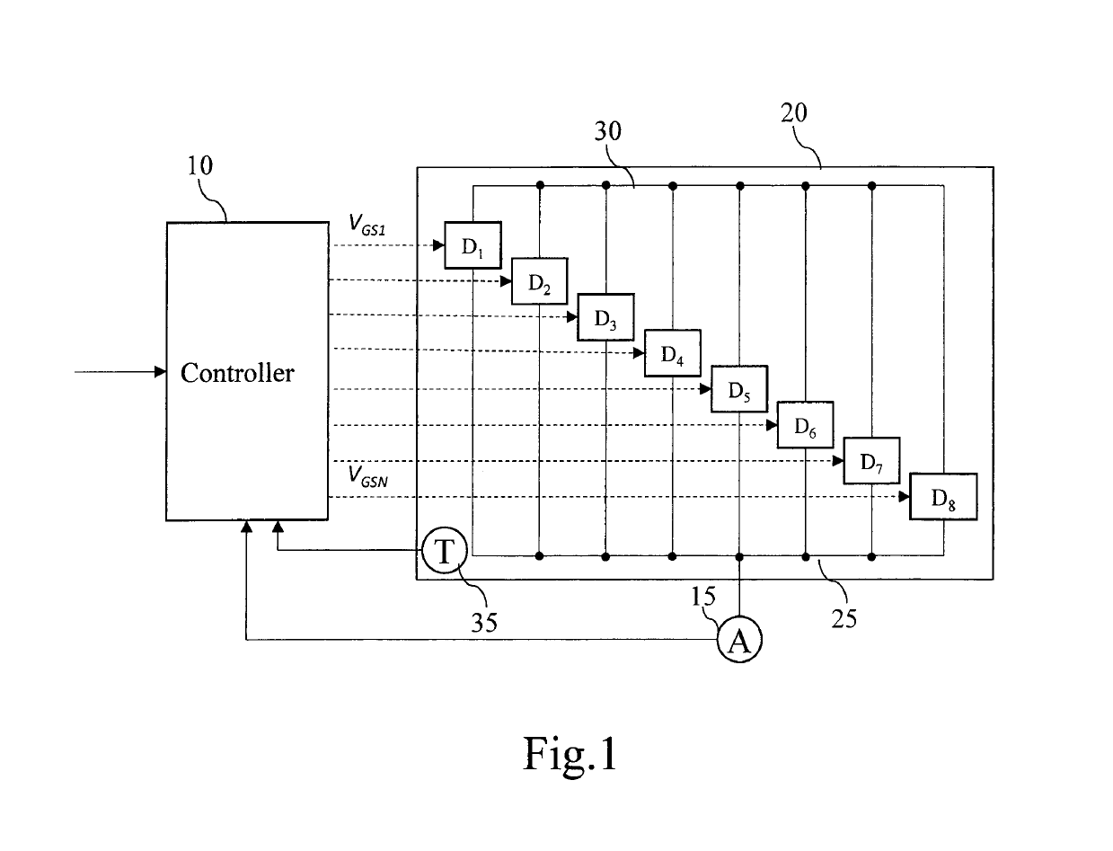
[0069]FIG. 1 represents an example of a system for controlling the operation of a multi-die power module according to the present invention.

[0070]The system for controlling the operation of a multi-die power module 20 comprises a controller 10 and a current sensor 15.

[0071]The multi-die power module 20 is for example composed of eight dies noted D1 to D8.

[0072]The controller 10 receives, from a host controller not shown in FIG. 1, an input control signal to be applied to the multi-die power module 20 and modifies it according to the current value sensed by the current sensor 15, the operating frequency of the input control signal, the duty cycle of the input control signal, a predetermined loss profile stored in the memory of the controller and eventually a table stored in the memory of the controller 10 and containing activation patterns for each die as it will be disclosed hereinafter.

[0073]As example, the input signal is modified by skipping at least one activation period so that...


PUM


Abstract

The present invention concerns a method for controlling the operation of a multi-die power module composed of at least two dies connected in parallel. The method comprises the steps of: —obtaining the current flowing in the multi-die power module, —obtaining a loss profile that is related to the dies of the multi-die power module, —estimating from the measured current flowing in the multi-die power module, the losses of one die when no die is passivated, when the die is passivated, and when at least one other die is passivated, —determining if and which die has to be passivated from the estimated losses and from the loss profile—passivating the die which has to be passivated if a die has to be passivated.

Description

TECHNICAL FIELD[0001]The present invention relates generally to a system and a method for controlling the operation of a multi-die power module.BACKGROUND ART[0002]Multi-die power modules are classically composed of several parallel connected power dies and are used for increasing the current capability over that of a single power die.[0003]For example, a three-phase converter is composed of four parallel power dies per switch, giving twenty four power dies in total.[0004]Emerging devices technologies, such as SiC (Silicon Carbide) and GaN (Gallium Nitride) Transistors, are typically realized in high current density, small power dies due to limitations of yield and cost of wafer substrate.[0005]In order to realize higher power SiC-based modules, a multitude of parallel connected SiC dies is necessary. Unlike parallel connected modules, parallel connected dies constitute a single switch that ideally commutates the same load current.SUMMARY OF INVENTIONTechnical Problem[0006]However, ...

Claims


Application Information

Patent Timeline
Patent Type & Authority Patents(United States)
IPC IPC(8): H02M1/088H03K17/08H02M1/32H03K17/12H03K17/14
CPCH02M1/088H02M1/32H03K17/14H03K17/12H03K17/08
Inventor VOYER, NICOLASEWANCHUK, JEFFREYMOLLOV, STEFAN
Owner MITSUBISHI ELECTRIC CORP
Features
  • R&D
  • Intellectual Property
  • Life Sciences
  • Materials
  • Tech Scout
  • Unparalleled Data Quality
  • Higher Quality Content
  • 60% Fewer Hallucinations
Learn More