Lamp body structure and panel lamp with positioning groove and power supply assembly therein

a technology of panel lamps and body structures, which is applied in the direction of lighting device details, lighting and heating equipment protection devices, etc., can solve the problems of excessive thickness of the entire lamp body, not good for packaging cost, and not aesthetically pleasing

Active Publication Date: 2020-07-14
SHENZHEN LONGHORN INTELLIGENT INSTR TECH CO LTD
View PDF5 Cites 5 Cited by
  • Summary
  • Abstract
  • Description
  • Claims
  • Application Information

AI Technical Summary

Benefits of technology

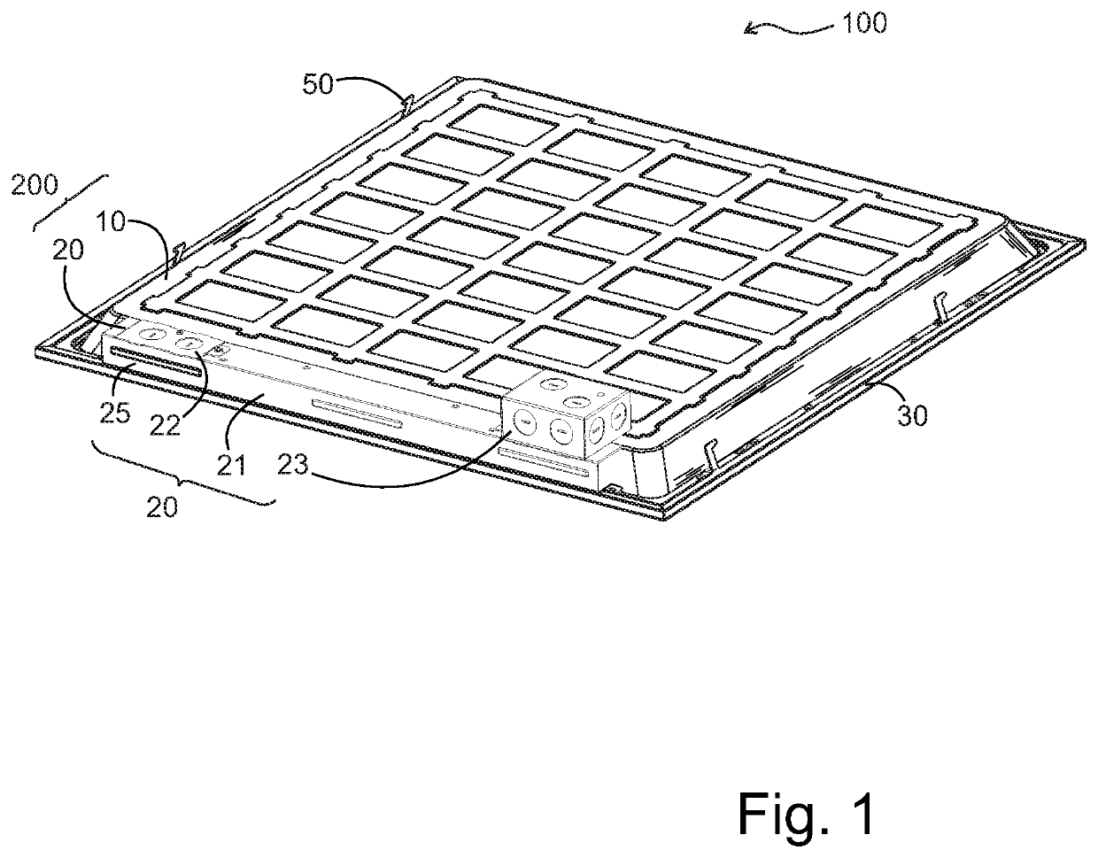
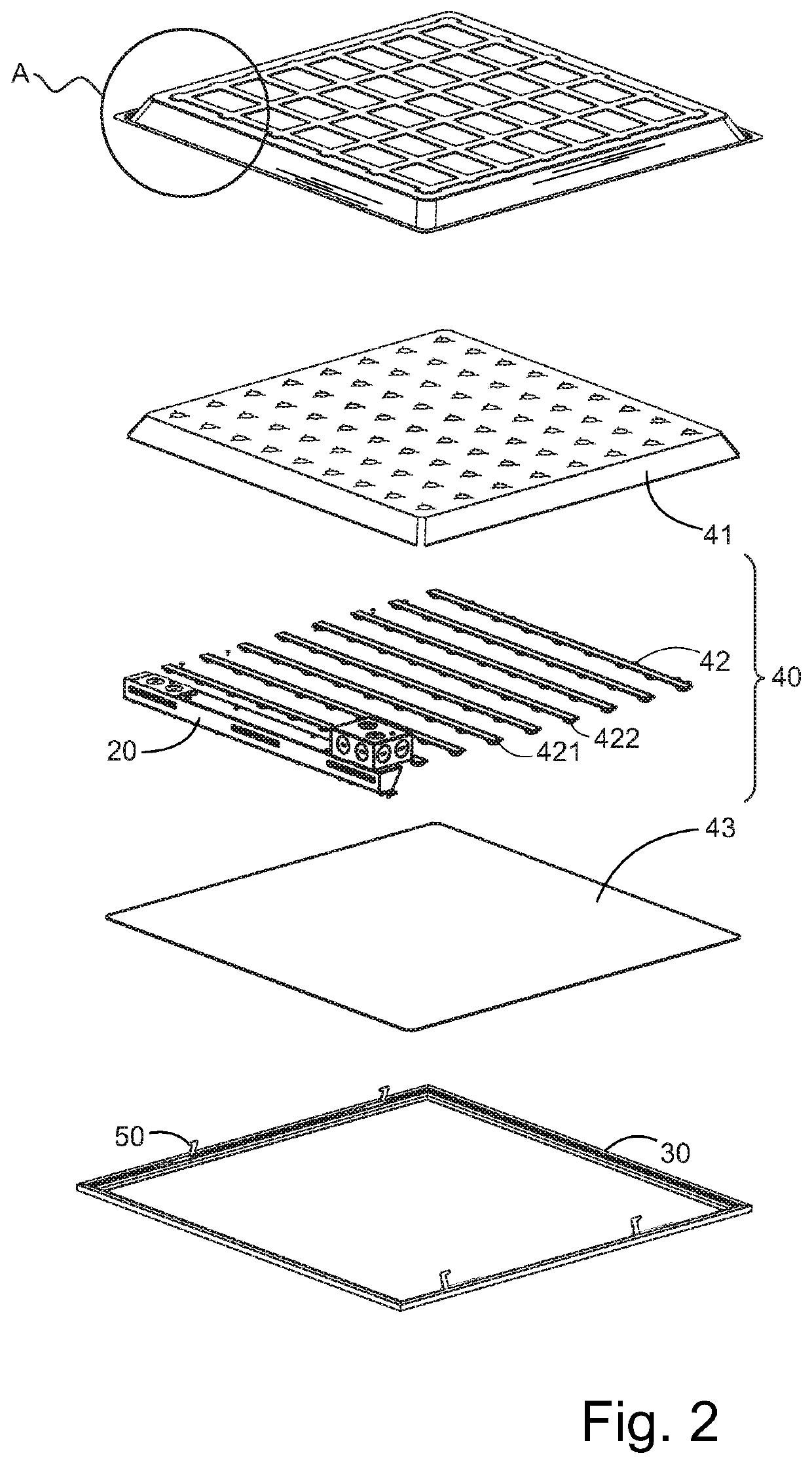
[0015]In one embodiment, the light source assembly includes reflective paper, LED light-emitting strips, and diffusion plates disposed in the chamber. The LED light-emitting strips are spaced apart from each other, and each of the LED light-emitting strips is located at the reflector. Between the paper and the diffuser plate, the reflective paper (reflector) is coupled to a cavity bottom of the seating cavity. In one embodiment, the panel light further includes a hook for connecting the middle frame structure to an outer structural member. One end of the hook is connected to the middle frame structure, and the other end of the hook is connected to an outer portion of a structural member. The hook and the power supply assembly are located on the same side of the support plate. The technical effect of the invention is that the lamp tray is laid flat, and a fixing groove is formed between the supporting plate and the corresponding side plate. The groove depth of the positioning groove is coincident with the thickness of the lamp plate, and one end of the power component is placed in the positioning groove. Therefore, the thickness space of the lamp panel can be utilized, and the overall thickness of the panel lamp can be reduced, so that the overall structure of the panel lamp is more novel and simple, and also contributes to the packaging and transportation of the panel lamp.
is that the lamp tray is laid flat, and a fixing groove is formed between the supporting plate and the corresponding side plate. The groove depth of the positioning groove is coincident with the thickness of the lamp plate, and one end of the power component is placed in the positioning groove. Therefore, the thickness space of the lamp panel can be utilized, and the overall thickness of the panel lamp can be reduced, so that the overall structure of the panel lamp is more novel and simple, and also contributes to the packaging and transportation of the panel lamp.

Problems solved by technology

A disadvantage of this construction is that it leads to an excessive thickness of the entire lamp body.
This is neither aesthetically pleasing nor good for the cost of packaging.

Method used


Image

  • Lamp body structure and panel lamp with positioning groove and power supply assembly therein
  • Lamp body structure and panel lamp with positioning groove and power supply assembly therein
  • Lamp body structure and panel lamp with positioning groove and power supply assembly therein

Examples


Embodiment Construction

[0053]The embodiments of the present invention are described in detail below, and the examples of the embodiments are illustrated in the drawings. The same or similar reference numerals are used to refer to the same or similar elements or elements having the same or similar functions. The embodiments described below with reference to the drawings are intended to be illustrative of the invention and are not to be construed as limiting.

[0054]In the description of the present invention, it is to be understood that the orientations or positional relationships indicated by the terms “thickness”, “upper”, “lower”, “vertical”, “parallel”, “bottom”, “corner”, etc. are based on the orientation or positional relationship shown in the figures and is for the convenience of the description of the invention and the simplification of the description, and is not intended to indicate or imply that the device or component referred to has a specific orientation, or is constructed and operated in a spe...


PUM


Abstract

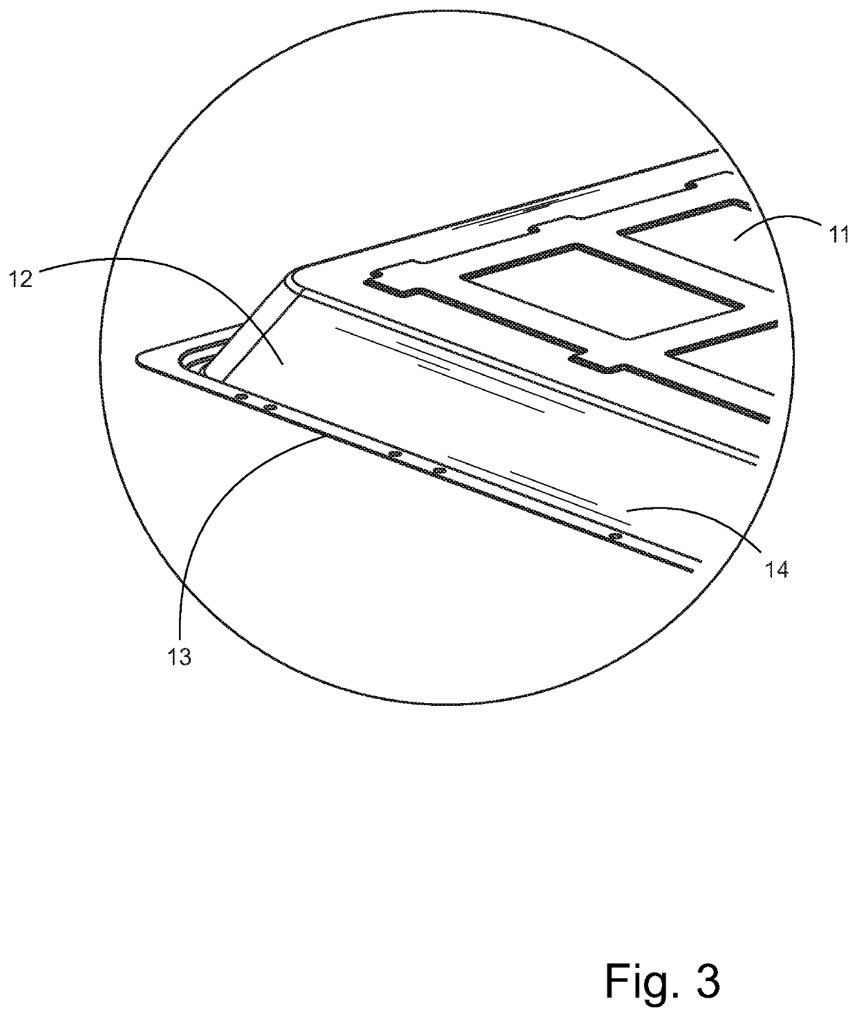
The lamp body structure includes a lamp panel and a power component. The lamp panel comprises a bottom plate and a plurality of side plates connected end to end. The bottom plate and each side plate together form a positioning cavity for the light source assembly, wherein the one side plate is located at the edge of the plate at the opening of the cavity and is disposed away from the bottom plate. The direction of the cavity extends and forms a support plate, and the support plate and the corresponding side plate together form a seating groove. The power component is connected to an external power source and supplies power to the light source component. One end of the power component is inserted into the mounting groove along the corresponding side plate and abuts the support plate.

Description

[0001]This application claims priority from earlier filed PCT application number PCT / CN2019 / 087817 entitled Lamp Body Structure And Panel Lamp by applicant Longhorn Intelligent Tech Co., Ltd. filed Jun. 6, 2019 having the same inventors. This application also claims priority from China Utility Model 201920738978.6 entitled Lamp Body Structure And Panel Lamp by applicant Longhorn Intelligent Tech Co., Ltd. filed May 21, 2019, also having the same inventors.FIELD OF THE INVENTION[0002]The present invention relates to the field of lighting technologies, and in particular, to a lamp body structure and a panel lamp.BACKGROUND[0003]At present, the direct-illuminated panel light on the market generally uses a metal shell power supply with a plurality of wiring holes, and the panel light can be connected to the power source through the metal shell power supply assembly. Different regions have different requirements for the location setting of power components. In the US market, metal shell ...

Claims


Application Information

Patent Timeline
Patent Type & Authority Patents(United States)
IPC IPC(8): F21V23/00F21K9/20F21V17/12F21V15/01F21V23/02F21Y105/00F21Y105/10F21Y105/16F21Y115/10
CPCF21V15/01F21V23/023F21V17/12F21V23/007F21K9/20F21Y2105/00F21Y2115/10F21Y2105/16F21Y2105/10F21V23/008
Inventor YANG, HAITAOYANG, LINLIU, MINLI, LEI
Owner SHENZHEN LONGHORN INTELLIGENT INSTR TECH CO LTD
Why Eureka
Try Eureka