Electromagnetic holding magnet and method for manufacturing, electromagnetic locking element and use of the same

a technology of electromagnetic locking element and magnetic holding magnet, which is applied in the direction of magnets, electromagnets with armatures, magnetic bodies, etc., can solve the problems of reducing the magnetic retaining flux in the central middle pole, completely stopping, etc., and achieves enhanced electromagnetic locking element, reduced triggering output, and easy and cost-effective manufacturing

Active Publication Date: 2020-08-04
KENDRION KUHNKE AUTOMATION
View PDF13 Cites 1 Cited by
  • Summary
  • Abstract
  • Description
  • Claims
  • Application Information

AI Technical Summary

Benefits of technology

[0008]The object is solved by an electromagnetic holding magnet comprising a yoke, a retaining plate interacting with the yoke as an anchor, at least one permanent magnet and a magnetic coil that encloses the yoke in sections, wherein the magnetic coil is configured in an energized state to at least reduce a magnetic retaining flux generated by the permanent magnet in the yoke and the retaining plate in order to at least reduce or eliminate a retaining force generated by the permanent magnet and release the retaining plate, wherein the electromagnetic holding magnet is further enhanced in that the yoke comprises a first yoke leg, a second yoke leg and a middle pole, wherein the yoke legs each conduct a partial flow of the magnetic retaining flux and are arranged symmetrically in relation to the middle pole and the magnetic coil that at least partially surrounds it.
[0037]The production of the electromagnetic holding magnet from flat parts enables a highly efficient production process. High-quality electromagnetic holding magnets can be manufactured with less technical effort. Involved finishing steps can be discarded. Furthermore, the same or similar advantages apply to the method according to aspects of the invention which were already mentioned with regard to the electromagnetic holding magnet itself, and repetitions will therefore be dispensed with.

Problems solved by technology

When the magnetic pole at least partially surrounding the middle pole is energized, this reduces the magnetic retaining flux in the central middle pole or causes it to completely cease.

Method used


Image

  • Electromagnetic holding magnet and method for manufacturing, electromagnetic locking element and use of the same
  • Electromagnetic holding magnet and method for manufacturing, electromagnetic locking element and use of the same
  • Electromagnetic holding magnet and method for manufacturing, electromagnetic locking element and use of the same

Examples


Embodiment Construction

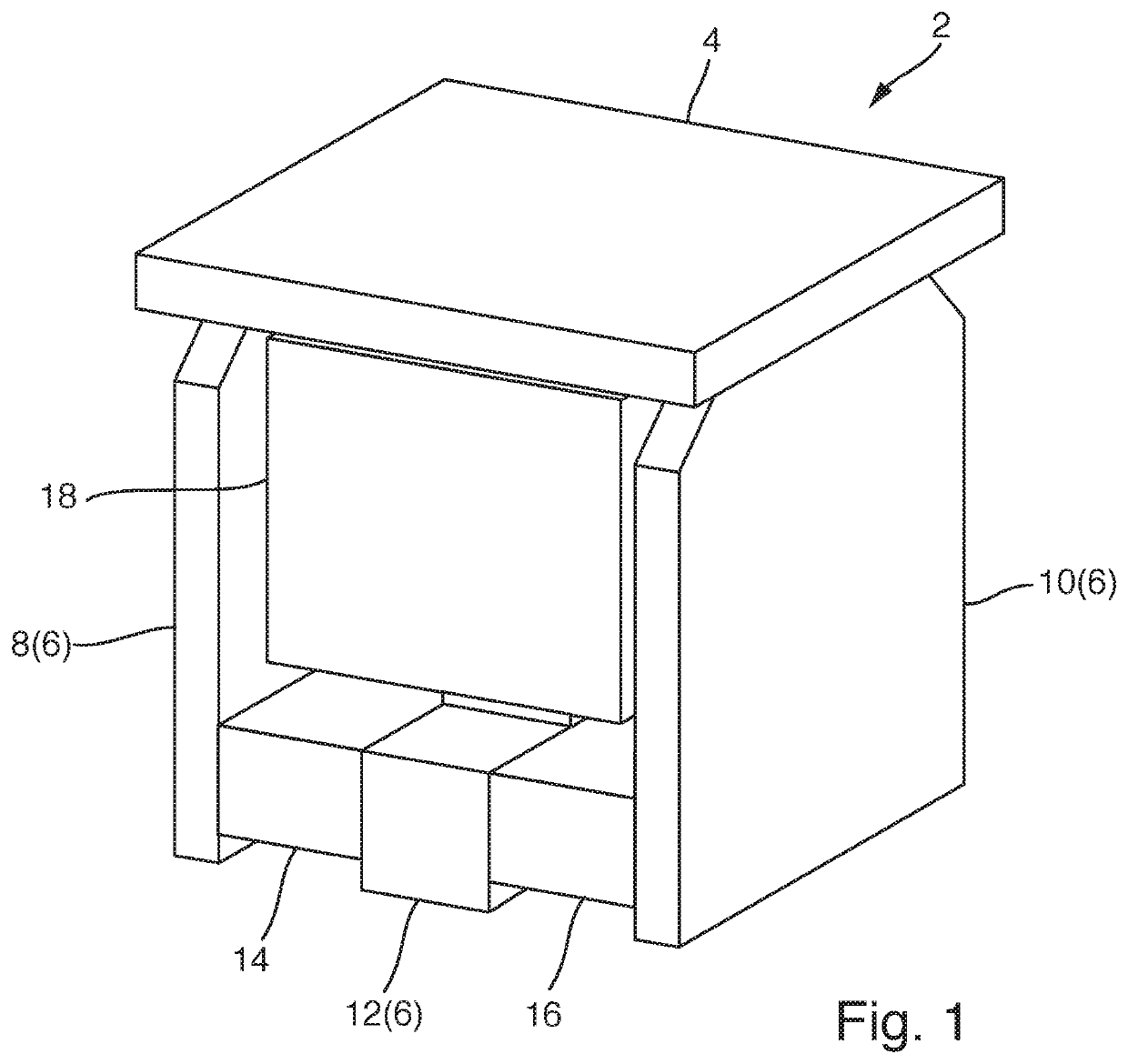
[0059]FIG. 1 shows an electromagnetic holding magnet 2 in a schematically simplified perspective representation. The electromagnetic holding magnet 2 comprises a retaining plate 4 that interacts as an anchor with a yoke 6. The yoke 6 comprises a first yoke leg 8, a second yoke leg 10 and a middle pole 12. The retaining plate 4, the first yoke leg 8, the second yoke leg 10 and the middle pole 12 are preferably manufactured from flat parts. These flat parts are preferably stamped parts. They are moreover preferably stamped from pre-annealed, corrosion-resistant or stainless sheet metal.

[0060]The electromagnetic holding magnet 2 furthermore comprises a first permanent magnet 14, a second permanent magnet 16 and a magnetic coil 18. The permanent magnets 14, 16 generate a magnetic retaining flux in the yoke 6 and the retaining plate 4 that holds the retaining plate 4 against the yoke 6. In an energized state, the magnetic coil 18 is configured to reduce this magnetic retaining flux gener...


PUM

PropertyMeasurementUnit
magnetic retaining fluxaaaaaaaaaa
retaining forceaaaaaaaaaa
corrosion-resistantaaaaaaaaaa

Abstract

An electromagnetic holding magnet and a method for manufacturing the same, and an electromagnetic locking element that, that in a preferred embodiment, is a lock in a container of an oxygen emergency supply system of an aircraft. The electromagnetic holding magnet includes a yoke and a retaining plate interacting with the yoke as an anchor. At least one permanent magnet generates a magnetic retaining flux in the yoke that includes a first yoke leg and a second yoke leg as well as a middle pole. The middle pole is surrounded in sections by a magnetic coil. The first and second yoke legs are arranged symmetrically in relation to the middle pole and the magnetic coil.

Description

PRIORITY[0001]This application claims priority to DE 10 2016 205 329.9, filed Mar. 31, 2016.BACKGROUND OF INVENTIONField of Invention[0002]The invention relates to an electromagnetic holding magnet comprising a yoke, a retaining plate that interacts with the yoke as an anchor, at least one permanent magnet, and a magnetic coil that encloses the yoke in sections, wherein in an energized state, the magnetic coil is configured to at least reduce a magnetic retaining flux generated by the permanent magnet in the yoke and the retaining plate in order to at least reduce or eliminate a retaining force generated by the permanent magnet and release the anchor. Moreover, the invention relates to an electromagnetic locking element comprising a base element, an opening element that can move relative to the base element and an electromagnetic holding magnet. In addition, the invention relates to the use of such an electromagnetic locking element. Furthermore, the invention relates to a method fo...

Claims


Application Information

Patent Timeline
Patent Type & Authority Patents(United States)
IPC IPC(8): E05B47/00H01F7/04E05C19/16H01F7/20H01F7/16H01F7/02
CPCE05B47/0038H01F7/0263H01F7/04E05B47/0006E05C19/166H01F7/20H01F7/1646H01F2007/1669E05B2047/0074
Inventor JOTTER, MATHIASPFEIFFER, BORGARTEUNIS, BLEIK
Owner KENDRION KUHNKE AUTOMATION
Why Eureka
Try Eureka