Cliff detection method, apparatus, and terminal device

a detection method and terminal device technology, applied in the field of robot technology, can solve problems such as poor reliability

Active Publication Date: 2020-08-11
UBTECH ROBOTICS CORP LTD
View PDF1 Cites 0 Cited by
  • Summary
  • Abstract
  • Description
  • Claims
  • Application Information

AI Technical Summary

Benefits of technology

[0036]As mention above, in this embodiment of the present disclosure, the detection distance matrix of the distances between the camera 100 of the target robot and the ground within the preset detection angle range collected by the camera 100 is obtained first, and then the difference matrix of the detection distance matrix and the corresponding theoretical distance matrix is calculated. Since the theoretical distance matrix is a pre-calculated distance matrix of the distances between the camera 100 and the horizontal ground within the detection angle range, which provides an accurate comparison basis for performing cliff detection. If the detection distance of a certain detection angle is greater than the theoretical distance, and the difference exceeds a certain threshold, it indicates that there is a sage on the ground within the detection angle. If this appears within multiple detection angles, that is, the amount of elements in the difference matrix which are greater than the preset first threshold is greater than the preset second threshold, it can be determined that there is a cliff area in front. Through the overall consideration of the distance matrix of the distances within the detection angle range, even if a certain part of the around changes its external conditions such as the color depth and the lightness, the influences on the overall detection result is extremely limited, which makes the detection result more accurate and reliable.

Problems solved by technology

In the detection method, since dark objects absorb more lights, the detection results will be largely changed with the change of external conditions, for example, the color depth and the lightness, of a certain part of the ground, which has poor reliability.

Method used


Image

  • Cliff detection method, apparatus, and terminal device
  • Cliff detection method, apparatus, and terminal device
  • Cliff detection method, apparatus, and terminal device

Examples


Embodiment Construction

[0011]In order to make those skilled in the an better understand the solutions of the present disclosure, the technical solutions in the embodiments of the present disclosure will be described clearly below with reference to the accompanying drawings in the embodiments of the present disclosure. Apparently, the described embodiments are merely part of the embodiments of the present disclosure, but not all of the embodiments. All other embodiments obtained by those skilled in the art based on the embodiments of the present disclosure without creative efforts shall fall within the protection scope of the present disclosure.

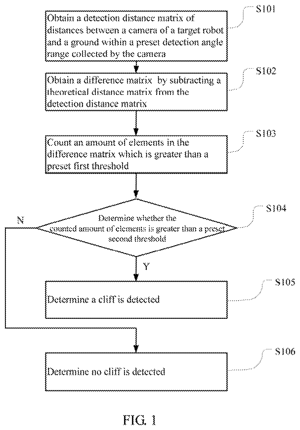
[0012]FIG. 1 is a flow chart of a cliff detection method according to an embodiment of the present disclosure. In this embodiment, the method is a computer-implemented method executable for a processor. As shown in FIG. 1, the method includes the following steps.

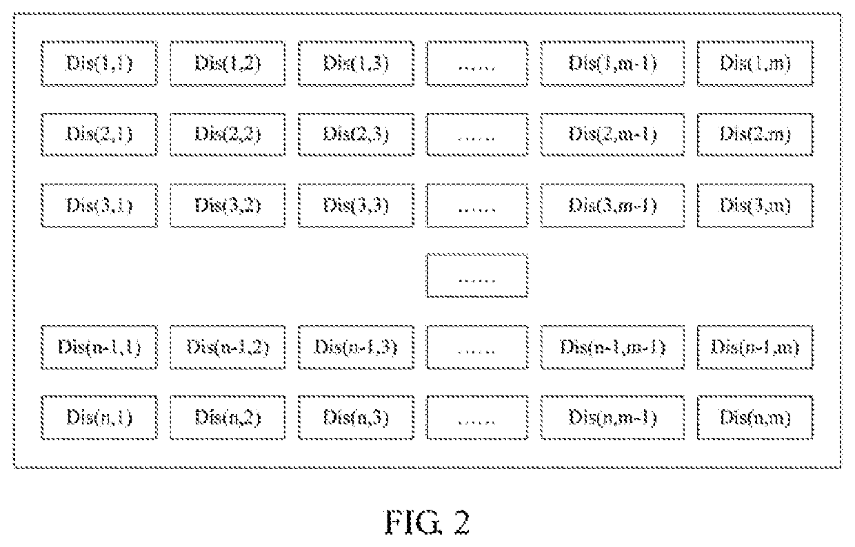
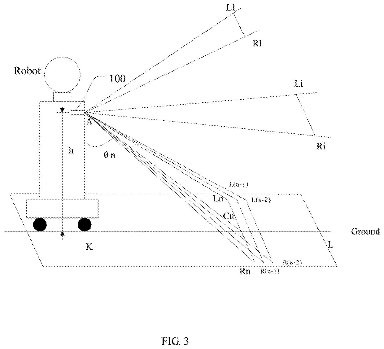
[0013]S101: obtaining a detection distance matrix of distances between a camera 100 (see FIG. 3) of a tar...


PUM


Abstract

The present disclosure provides a method, apparatus, and terminal device for cliff detection. The method includes: obtaining a detection distance matrix of distances between a camera of a target robot and a ground within a preset detection angle range collected by the camera; obtaining a difference matrix obtained by subtracting a theoretical distance matrix from the detection distance matrix; counting an amount of elements in the difference matrix being greater than a preset first threshold; and determining a cliff is detected if the counted amount of the elements is greater than a preset second threshold. Through the overall consideration of the distance matrix of the distances within the detection angle range, even if a certain part of the ground changes its external conditions such as the color depth and the lightness, the influences on the overall detection result is extremely limited, which makes the detection result more accurate and reliable.

Description

CROSS REFERENCE TO RELATED APPLICATIONS[0001]This application claims priority to Chinese Patent Application No. 201711435033.9, filed Dec. 26, 2017, which is hereby incorporated by reference herein as if set forth in its entirety.BACKGROUND1. Technical Field[0002]The present disclosure relates to robot technology, and particularly to a cliff detection method, apparatus, and terminal device.2. Description of Related Art[0003]Cliff detection means a test which a robot determines whether it came to the edge of the ground, so as to prevent the robot from falling from the edge of the ground. The robots of the prior art generally detects a particular location in front through an infrared distance sensor. The robot control system of the robots determines that whether to stop going forward or go around the hollow area in front basing on the detection result. In the detection method, since dark objects absorb more lights, the detection results will be largely changed with the change of exter...

Claims


Application Information

Patent Timeline
Patent Type & Authority Patents(United States)
IPC IPC(8): G05D1/02G06T7/00
CPCG05D1/0223G05D1/0248G05D1/0238G06T7/00G05D1/0246B25J9/1666G06T7/77G06T1/0014G01C11/02G06T2207/10028G06T7/74G06T2207/30261G06T7/254
Inventor XIONG, YOUJUNHUANG, GAOBOHU, JIAWEN
Owner UBTECH ROBOTICS CORP LTD
Why Eureka
Try Eureka