
Intra-increment adjustments of implicit finite element simulation

a finite element and implicit technology, applied in the field of computer programs and systems, can solve the problems of non-physical numerical effects, excessive number of iterations performed for a given load increment, etc., and achieve the effect of high penalty stiffness and efficient improvement of finite element simulation accuracy

Active Publication Date: 2020-08-11
DASSAULT SYSTEMES SIMULIA CORP
View PDF6 Cites 0 Cited by
  • Summary
  • Abstract
  • Description
  • Claims
  • Application Information

AI Technical Summary

Benefits of technology

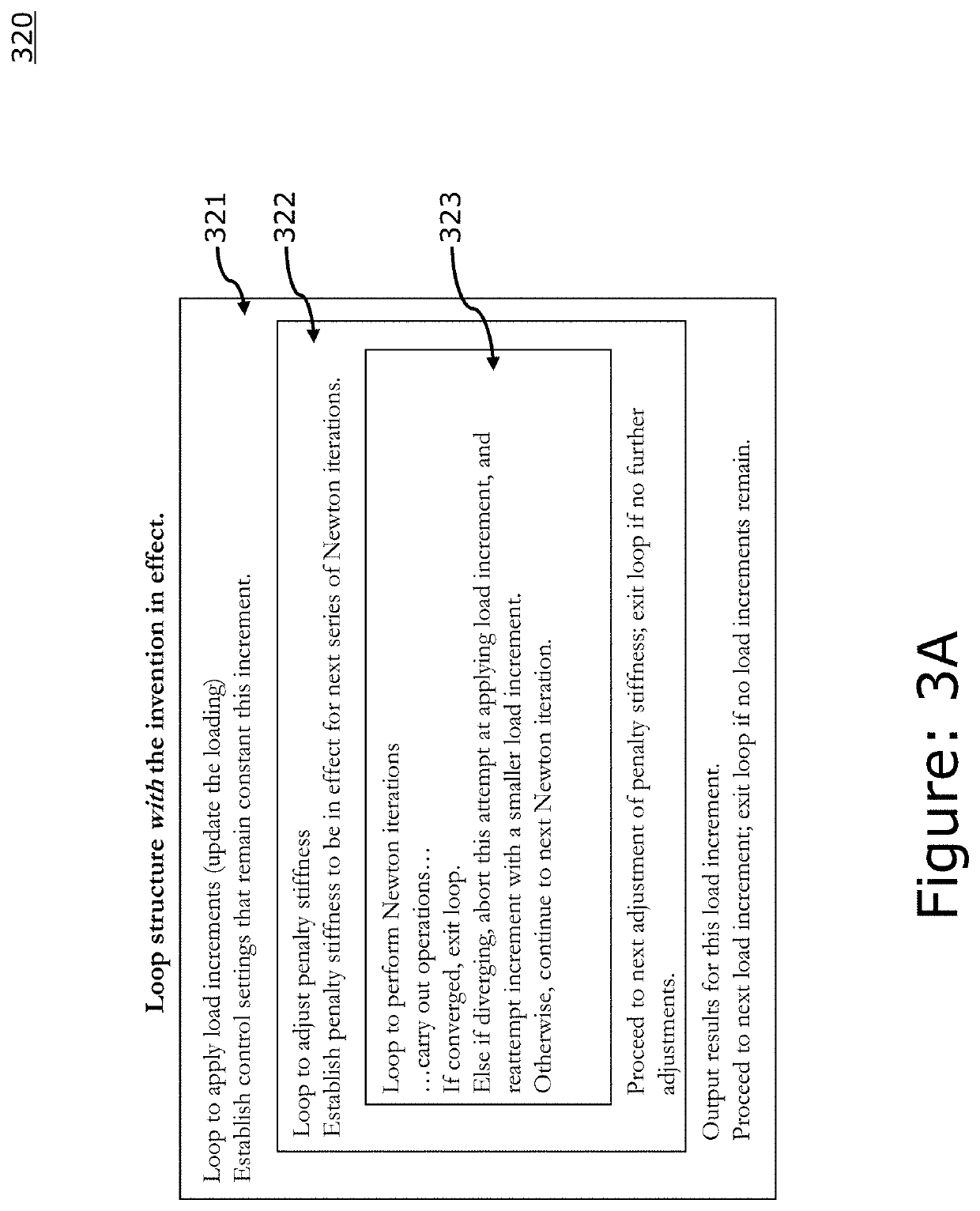
[0009]Thus, a method of efficiently improving the accuracy of finite element simulation is needed. Embodiments of the present invention allow converged solutions of a finite element simulation to always correspond to having, for example, a high penalty stiffness, in effect, so the user can consistently rely on the results being accurate.
[0011]Embodiments of the present invention mitigate these errors and provide realistic nonlinear finite element simulations. The present invention allows the reported solution to be free of potential inaccuracies associated with numerical control settings (such as a finite contact (penalty) stiffness or nonzero contact stabilization stiffness) that may degrade accuracy. Thus, the invention can help to avoid tradeoffs between accuracy and robustness for simulations, and it can help to make realistic finite element simulation more accessible to non-expert users.

Problems solved by technology

With the above mentioned augmented penalty method, the overall number of iterations performed for a given load increment can be excessively large and non-physical numerical effects will persist to some degree in reported solutions.
Non-physical numerical effects with the augmented penalty method include contact penetrations of distances up to the penetration tolerance threshold and contact pressures occurring where a small gap exists between surfaces.

Method used


Image

  • Intra-increment adjustments of implicit finite element simulation
  • Intra-increment adjustments of implicit finite element simulation
  • Intra-increment adjustments of implicit finite element simulation

Examples


Embodiment Construction

[0037]A description of example embodiments of the invention follows.

[0038]The teachings of all patents, published applications and references cited herein are incorporated by reference in their entirety.

[0039]The present invention allows for a more efficient determination of an accurate solution to a finite element simulation. Embodiments of the present invention include the possibility of precise strict enforcement of contact constraints, unlike the augmented penalty method, which is described hereinabove. While example embodiments described herein are discussed as being used in a finite element simulation to improve contact finite element simulations, embodiments of the present invention are not so limited. The principles behind Applicant's approach to finite element simulation can be applied to features other than the contact constraint enforcement method, such as artificial stabilization methods, to benefit from these methods' positive attributes, e.g. improved convergence, with...


PUM


Abstract

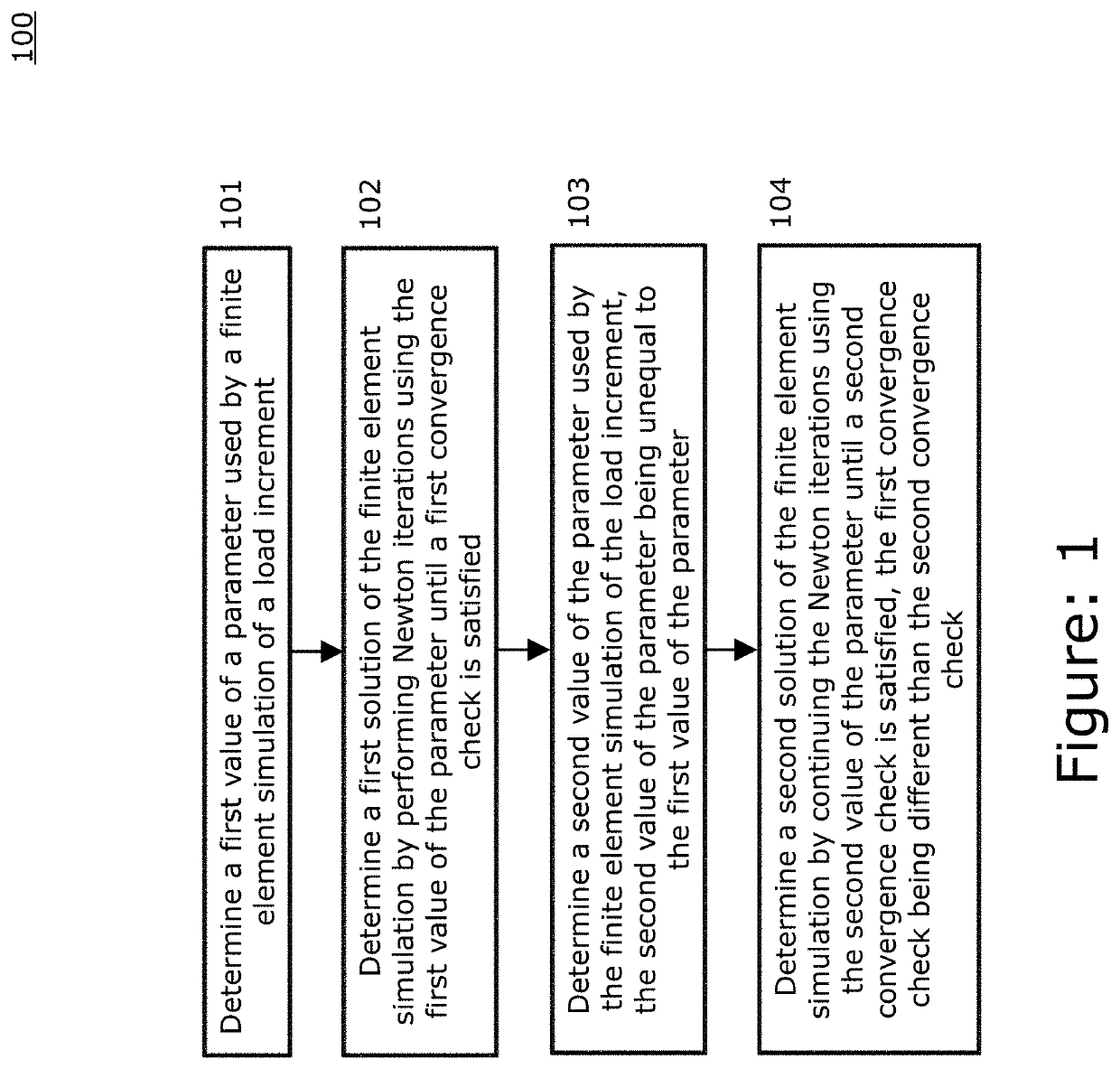
An embodiment of the invention involves increasing the penalty stiffness within a finite element simulation increment, which is more accurate because it avoids following a solution path with significant non-physical penetrations. An embodiment of the present invention begins by determining a first value of a parameter used by a finite element simulation of a load increment. Next, a first solution of the finite element simulation is determined by performing Newton iterations using the first value of the parameter until a first convergence check is satisfied. Then, a second value the parameter is determined wherein the second value of the parameter is unequal to the first value of the parameter. Finally, a second solution of the finite element simulation is determined by continuing the Newton iterations using the second value of the parameter until a second convergence check is satisfied, the first convergence check being different than the second convergence check.

Description

BACKGROUND OF THE INVENTION[0001]The invention generally relates to the field of computer programs and systems, and specifically to the field of computer aided design (CAD), computer-aided engineering (CAE), modeling, and simulation.[0002]A number of systems and programs are offered on the market for the design of parts or assemblies of parts. These so called CAD systems allow a user to construct and manipulate complex three-dimensional models of objects or assemblies of objects. CAD systems thus provide a representation of modeled objects using edges or lines, in certain cases with faces. Lines, edges, faces, or polygons that make up models may be represented in various manners, e.g., non-uniform rational basis-splines (NURBS).[0003]These CAD systems manage parts or assemblies of parts of modeled objects, which are mainly specifications of geometry. In particular, CAD files contain specifications, from which geometry is generated. From geometry, a representation is generated. Speci...

Claims


Application Information

Patent Timeline
Patent Type & Authority Patents(United States)
IPC IPC(8): G06F30/23
CPCG06F30/23
Inventor HARKNESS, HARRINGTON HUNTER
Owner DASSAULT SYSTEMES SIMULIA CORP
Learn More