System for controling internal combustion engine

a technology of internal combustion engine and controller, which is applied in the direction of combustion engine, internal combustion piston engine, machine/engine, etc., can solve the problems of low likelihood bypass valve opening, and error in determining the accuracy of surging, so as to prevent the occurrence of surging. , the effect of determining the accuracy of occurrence of surging

Active Publication Date: 2020-08-25
HONDA MOTOR CO LTD
View PDF21 Cites 0 Cited by
  • Summary
  • Abstract
  • Description
  • Claims
  • Application Information

AI Technical Summary

Benefits of technology

[0015]Accordingly, by calculating the opening ratio based on the speed of the internal combustion engine and making the second opening determination on the basis of an amount of change in the calculated opening ratio, the second opening determination can be made accurately while favorably reflecting the degree of variation in the compressor flow rate. As a result, the determination accuracy of occurrence of surging by the first and second opening determinations as a whole is improved, whereby the effect of the first embodiment of avoiding unnecessary opening of the air bypass valve and surely preventing occurrence of surging can be achieved more favorably.

Problems solved by technology

According to this configuration, when the flow rate of a compressor decreases while the opening of the throttle valve is unchanged, for example, in the first opening determination based on the compressor flow rate, it may be erroneously determined that the air bypass valve should be opened, even though the likelihood of occurrence of surging is low.
Meanwhile, when the compressor flow rate is hardly decreased while the throttle valve is closed, for example, in the second opening determination, it may be erroneously determined that the air bypass valve should be opened, even though the likelihood of occurrence of surging is low.

Method used


Image

  • System for controling internal combustion engine
  • System for controling internal combustion engine
  • System for controling internal combustion engine

Examples


Embodiment Construction

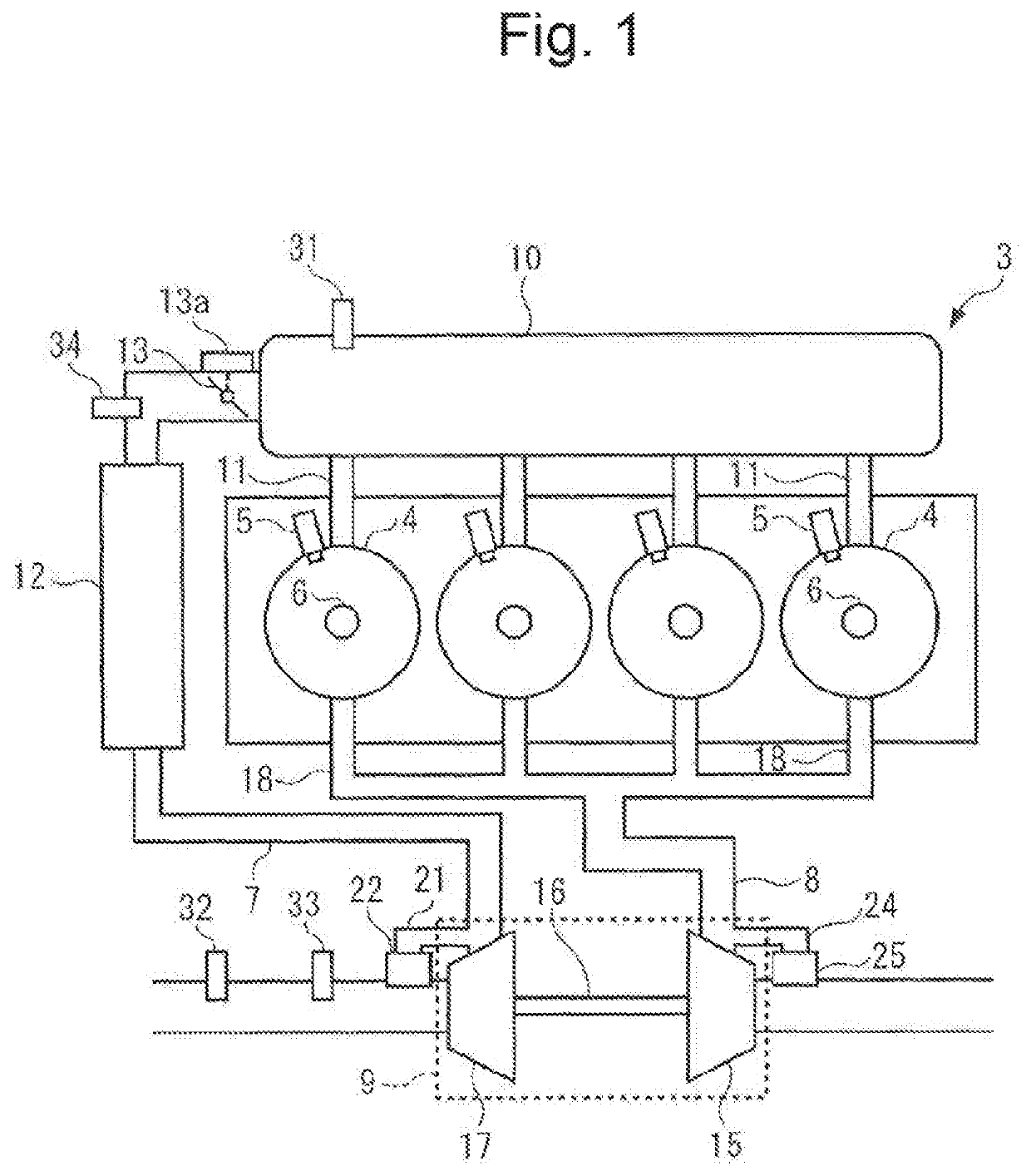
[0025]Hereinafter, preferred embodiments of the present invention will be described with reference to the drawings. An internal combustion engine (referred to as “engine” below) 3 illustrated in FIG. 1 has four cylinders 4, is a direct-injection gasoline engine in which fuel is directly injected into a combustion chamber (not shown), and is mounted on a vehicle (not shown). Additionally, the engine 3 is connected to a driving wheel and the like through a stepped automatic transmission (none of the parts are shown).

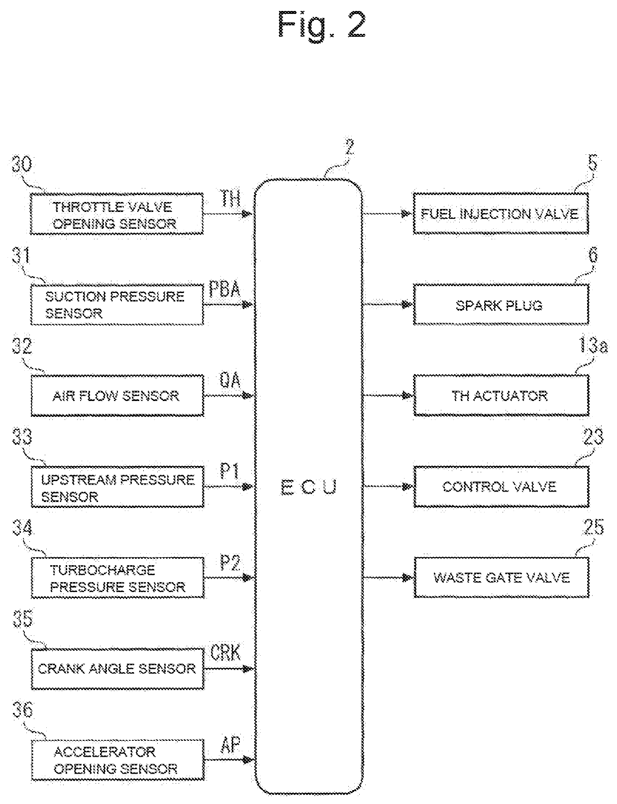
[0026]A fuel injection valve 5 and a spark plug 6 are provided in each cylinder 4. An ECU (electronic control unit) 2 (see FIG. 2) controls the open time and open timing of the fuel injection valve 5, and the ignition timing of the spark plug 6.

[0027]The engine 3 includes an intake valve, an exhaust valve, and a piston (none of the parts are shown) for each cylinder 4, and also includes an intake passage 7, an exhaust passage 8, and a turbo charger 9. The intake passage 7 ...


PUM


Abstract

In a system for controlling an internal combustion engine, first opening determination of determining whether to open an air bypass valve 22 on the basis of a compressor flow rate (target compressor flow rate QAIRCMD) passing through a compressor 17 and a compressor front-rear pressure ratio P2 / P1, and second opening determination of determining whether to open the air bypass valve 22 on the basis of an opening ratio reduction amount DRTHO as a reduction amount of an opening ratio RTHO of a throttle valve 13 are performed. The air bypass valve 22 is opened when it is determined in both of the first opening determination and the second opening determination that the air bypass valve 22 should be opened.

Description

CROSS-REFERENCE OF RELATED APPLICATION[0001]This application claims priority of Japanese Patent Application No. 2017-213712 filed in Japan on Nov. 6, 2017, the entire contents of which incorporated herein by reference.TECHNICAL FIELD[0002]The present invention relates to a system with a controller of an internal combustion engine including a turbocharger having a compressor that compresses intake air, and an air bypass valve that opens and closes a bypass passage that bypasses the compressor.BACKGROUND OF THE INVENTION[0003]In an internal combustion engine having a turbocharger, when a throttle valve arranged on the downstream side of a compressor is closed during a transition period from turbocharged operation to deceleration operation, the turbocharge pressure on the downstream side of the compressor increases even more between the compressor and the throttle valve, and the flow rate of air passing through the compressor is reduced. For this reason, surging of the compressor occur...

Claims


Application Information

Patent Timeline
Patent Type & Authority Patents(United States)
IPC IPC(8): F02B37/16F02B37/12
CPCF02B37/16F02B2037/125Y02T10/12
Inventor IIDA, TETSUYATSUTSUMI, YUJIROHORIBA, AYUMU
Owner HONDA MOTOR CO LTD
Why Eureka
Try Eureka