Liquid ejecting apparatus having a light sensor for detecting when a recording medium is raised from a support unit

a technology of light sensor and liquid ejecting apparatus, which is applied in the direction of printing, other printing apparatus, etc., can solve the problems of inability to detect the failure of the transport of the target, the inability to adequately transport the target along the direction of transport, and the damage of the target, so as to improve the determination accuracy

Inactive Publication Date: 2015-02-24
SEIKO EPSON CORP
View PDF7 Cites 0 Cited by
  • Summary
  • Abstract
  • Description
  • Claims
  • Application Information

AI Technical Summary

Benefits of technology

[0013]An advantage of some aspects of the invention is that there is provided a liquid ejecting apparatus which achieves improvement of determination accuracy whether or not a portion of a target supported by a supporting unit which is at least part of a supported portion opposing a movable area of a moving body is separated from the supporting unit.
[0015]In this configuration, the light-emitting portion arranged at one of the first and second positions emits light toward the other one of the first and second positions. The light from the light-emitting portion as described above is received by the light-receiving portion when the entire part of the supported portion of the target is in contact with the supporting unit, it is determined that the supported portion of the target is not separated from the supported portion of the target. In contrast, in a case where at least part of the supported portion of the target is separated from the supported unit, if a region of the supported portion separated from the supporting unit (hereinafter, referred to as a “separated region”) is located between the first position and the second position, the light from the light-emitting portion is blocked or changed in direction of travel by the separated region. Consequently, the light-receiving quantity at the light-receiving portion is lowered, and it is determined that the separated region is generated in the target. In other words, the fact that the separated region is generated may be determined even in a case where the separated region is generated in the supported portion of the target at the time other than the transport failure of the target, Therefore, accuracy of determination of whether or not at least part of a target supported by a supporting unit and opposing a movable area of a moving body is separated from the supporting unit is improved.
[0018]At this point, in the invention, the direction of travel of the light from the light-emitting portion intersects the scanning direction of the moving body. Therefore, the probability that the light from the light-emitting portion enters the separated region of the supported portion is higher than the case where the direction of travel of the light from the light-emitting portion matches the scanning direction of the moving body. Consequently, accuracy of the determination of whether or not the separated regions are generated in the supported portion of the target is improved.
[0020]In this configuration, when performing a determining process in a state in which the moving body is located at a reference position, the existence of the separated regions in the supported portion of the target is determined before starting the movement from the reference position of the moving body. When the determining process is performed in a state in which the moving body moves from the reference position, whether or not the separated region exists is determined before the moving body during the movement comes into contact with the target, or whether or not the separated region exists is determined quickly after the contact. Therefore, when it is configured to prohibit the movement of the moving body when it is determined that the separated regions exist, the contact between the moving body and the target may be avoided, or the degree of breakage of the target in association with the contact between the moving body and the target may be minimized.

Problems solved by technology

However, when the transport failure of the target or the like occurs, there is a probability that the target cannot be adequately transported along the direction of transport, and at least part of the supported portion of the target may be separated from the supporting unit toward the carriage, that is, at least part of the supported portion is separated upward from the supporting unit.
When the movement of the carriage is continued without detecting such a contact, the target may become damaged due to the movement of the carriage in a state of being kept in contact with the target.
When detecting the fact that at least part of the supported portion of the target is separated from the supporting unit using the method described in JP-A-2000-1012, a problem as shown below may occur.
In addition, the transport failure of the target is not detected unless time of a certain extent is elapsed since the detection of the leading end of the target by the first detecting system, the transport failure of the target is not detected.
Therefore, there is a probability that the carriage moves in a state of being in contact with the target and hence the target becomes damaged or the degree of the damage is increased during a period from when the transport failure actually occurs until the transport failure is detected.
Also, separating of at least part of the supported portion of the target from the supporting unit may occur at the time other than the transport failure of the target represented by, so-called, the paper jam.
For example, in the liquid ejecting apparatus of a type in which the liquid ejecting head is not mounted on the moving body, when the contact between the moving body and the target cannot be detected, the target may be subjected to a damage or increase in degree of the damage due to the movement of the movable member in a state in which the contact with the target is maintained in the same manner as the case of the liquid ejecting apparatus of the type in which the liquid ejecting head is mounted on the moving body.
When the direction of travel of the light from the light-emitting portion matches the scanning direction of the moving body, erroneous determination that the separated region is not generated may occur in the state shown below even when the separated region is generated in the supported portion of the target.
As a result, even when the separated regions are actually generated in the supported portion of the target, the separated region is not detected by using the light-detecting unit.
When the direction of travel of the light is set on the basis of a case where the liquid ejecting head is located at a position close to the first position, there is a probability that the fact that the separated regions exist in the target cannot be detected when the liquid ejecting head is located at a position close to the reference position.

Method used


Image

  • Liquid ejecting apparatus having a light sensor for detecting when a recording medium is raised from a support unit
  • Liquid ejecting apparatus having a light sensor for detecting when a recording medium is raised from a support unit
  • Liquid ejecting apparatus having a light sensor for detecting when a recording medium is raised from a support unit

Examples


Embodiment Construction

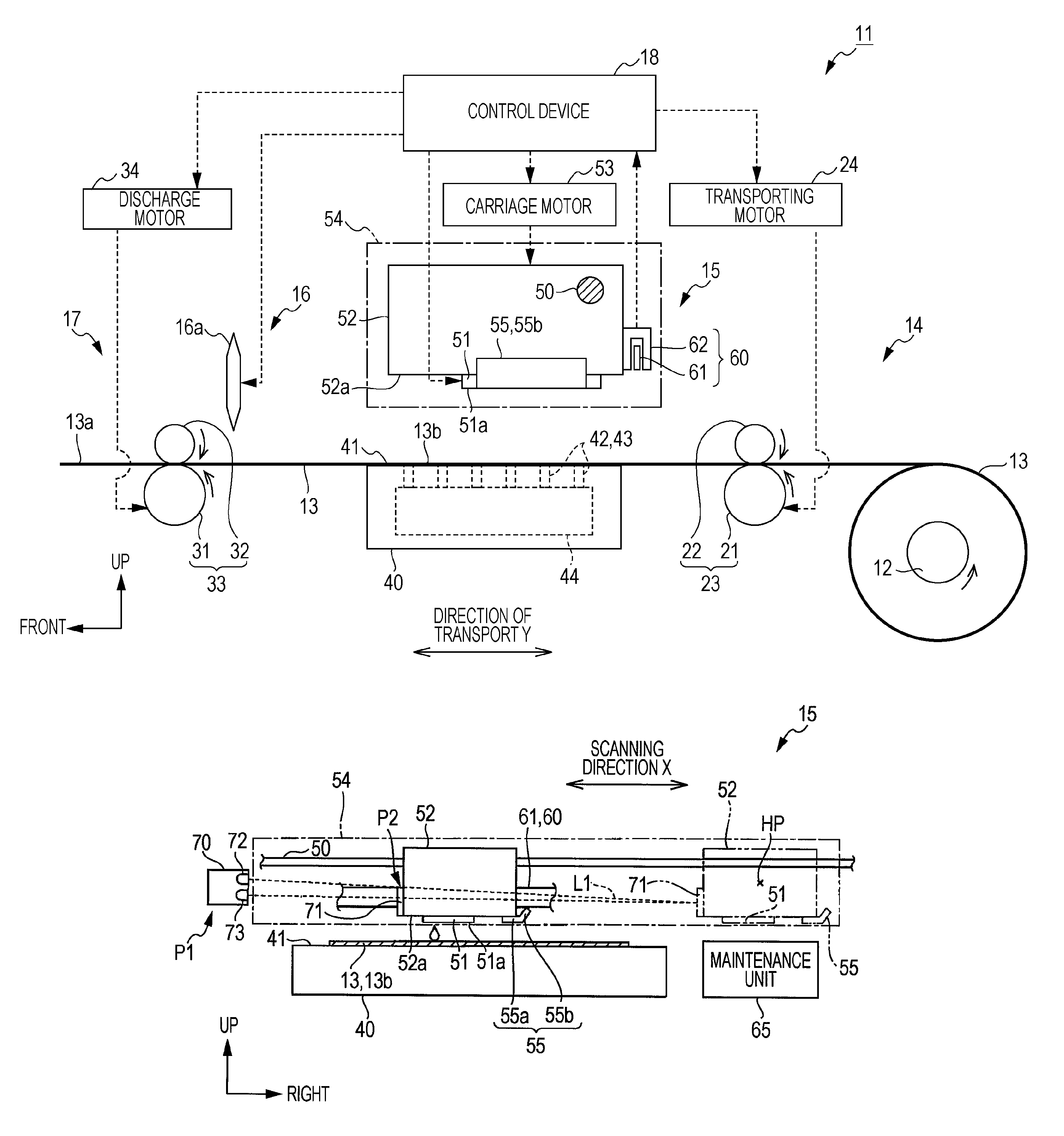
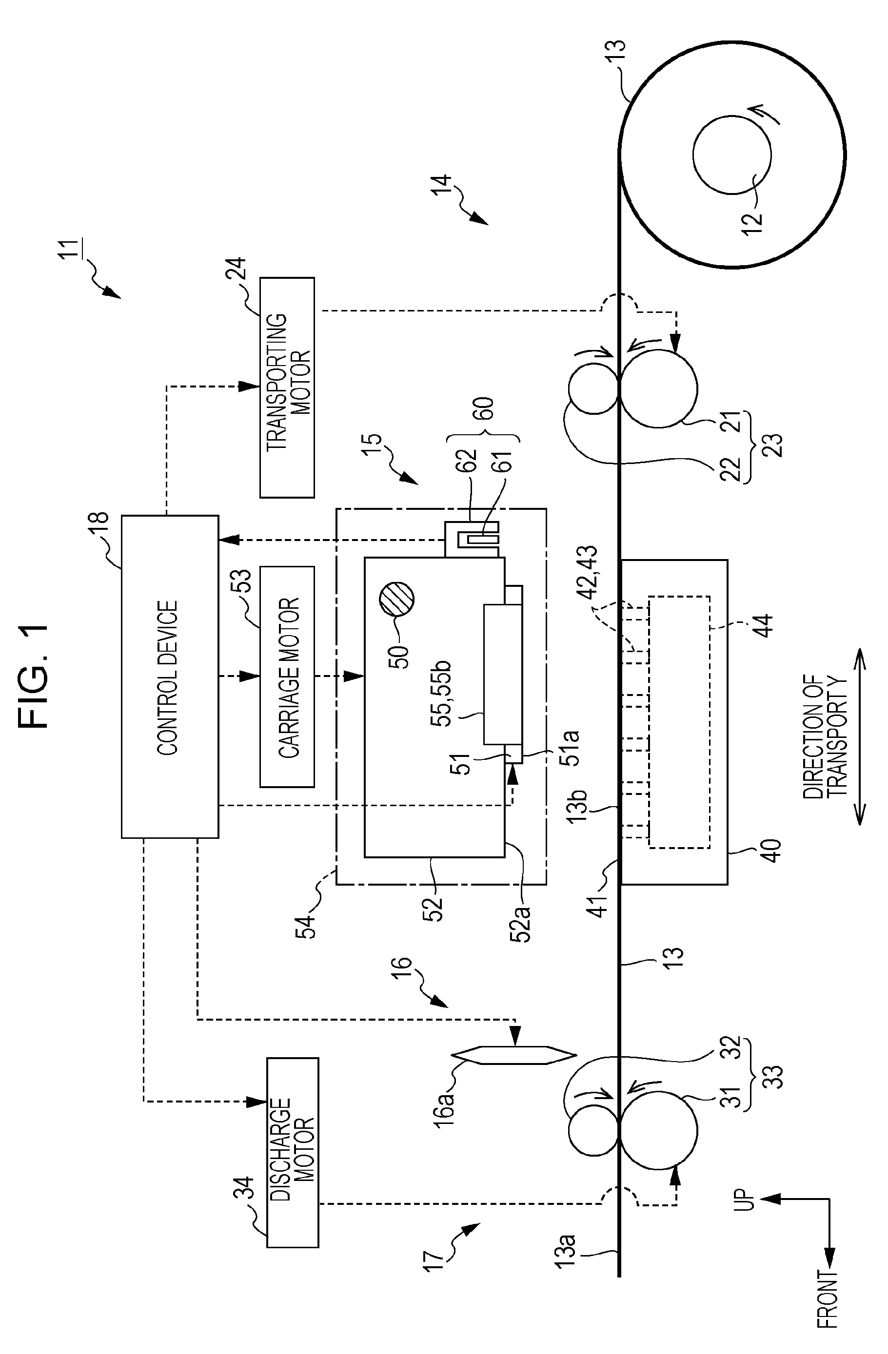
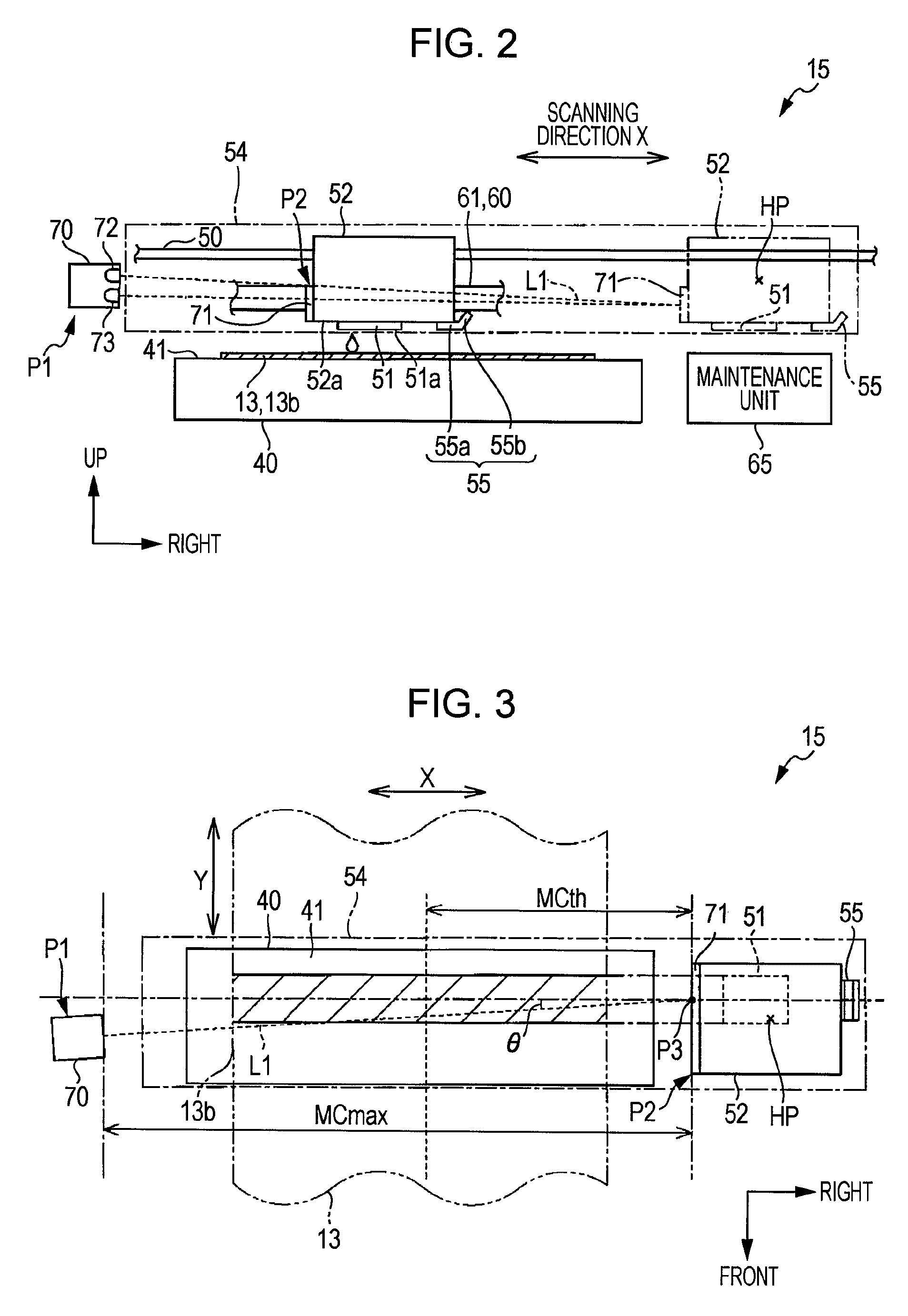
[0037]Referring now to FIG. 1 to FIG. 6, an embodiment in which the invention is embodied will be described. In the following description of this specification, “front and back directions”, “up and down directions”, and “left and right directions” indicate “front and back directions”, “up and down directions”, and “left and right directions” indicated by arrows in FIG. 1, FIG. 2 and FIG. 3, respectively.

[0038]As shown in FIG. 1, an ink jet printer 11 as an example of a liquid ejecting apparatus is an apparatus configured to form an image on a roll paper 13 wound around a revolving shaft 12 extending in the lateral direction as a direction orthogonal to a paper plane into a roll form as an example of a target by adhering ink as an example of liquid on the roll paper 13. The ink jet printer 11 in this configuration includes a transporting portion 14 configured to transport the roll paper 13 fed by the rotation of the revolving shaft 12 around which the roll paper 13 is wound countercl...


PUM


Abstract

A liquid ejecting apparatus including: a liquid ejecting head configured to eject liquid to a target; a supporting unit configured to support the target; a light-detecting unit arranged so that a transporting route is located between the supporting unit and the light-detecting unit in a prescribed direction in which the supporting unit and the target supported by the supporting unit are arranged when the supporting unit supports the target, and including a light-emitting portion configured to emit light and a light-receiving portion configured to receive the light from the light-emitting portion; and a determining unit configured to determine whether or not at least part of a supported portion of the target supported by the supporting unit is separated from the supporting unit on the basis of the light-receiving quantity at the light-receiving portion.

Description

[0001]This application claims priority to Japanese Patent Application No. 2011-178932 filed on Aug. 18, 2011. The entire disclosure of Japanese Patent Application No. 2011-178932 is hereby incorporated herein by reference.BACKGROUND[0002]1. Technical Field[0003]The present invention relates to a liquid ejecting apparatus such as an ink jet printer.[0004]2. Related Art[0005]In general, as a printing apparatus having a detection system for detecting a jam of printing paper (also referred to as “paper jam”) transported along a predetermined direction of transport, an apparatus in which a plurality of the detection systems are arranged along a transporting route for printing paper is known (see JP-A-2000-1012). The detecting systems described above include a light-emitting portion configured to emit light and a light-receiving portion configured to receive light, respectively. Then, one of the light-emitting portion and the light-receiving portion is arranged on a back surface (that is,...

Claims


Application Information

Patent Timeline
Patent Type & Authority Patents(United States)
IPC IPC(8): B41J29/393B41J11/00
CPCB41J11/006B41J11/0095
Inventor HARA, OSAMUSASAKI, TSUNEYUKI
Owner SEIKO EPSON CORP
Why Eureka
Try Eureka