
Control apparatus for internal combustion engine

a control apparatus and internal combustion engine technology, applied in the direction of electric control, machines/engines, instruments, etc., can solve the problems of affecting the accuracy of making a determination on the occurrence of disturbances, and affecting the accuracy of making a determination. , to achieve the effect of reducing the accuracy of making a determination

Active Publication Date: 2018-10-09
TOYOTA JIDOSHA KK
View PDF5 Cites 0 Cited by
  • Summary
  • Abstract
  • Description
  • Claims
  • Application Information

AI Technical Summary

Benefits of technology

The patent text describes a control apparatus for an internal combustion engine that can accurately determine when a disturbance occurs. This is important because this control apparatus can prevent the accuracy from deteriorating over time. By analyzing the rotational speed signal, the control apparatus can determine if there is a disturbance based on the amplitude of certain components. This allows for stable engine operation and ensures that the control apparatus remains accurate in detecting disturbances.

Problems solved by technology

In some cases, a disturbance may occur in an internal combustion engine as a result of running on a rough road.
As a result, the accuracy in making a determination on the occurrence of a disturbance may deteriorate.
Besides, the fluctuation rate of the rotational speed of the internal combustion engine may also change due to a factor other than a disturbance, for example, an unstable combustion state.
In this case as well, the accuracy in making a determination on the occurrence of a disturbance may deteriorate.
Besides, even when the first-order parameter is equal to or larger than the first threshold, the amplitude of the first-order and lower-order than the first-order components may increase as a result of the unstableness of combustion instead of the disturbance.

Method used


Image

  • Control apparatus for internal combustion engine
  • Control apparatus for internal combustion engine
  • Control apparatus for internal combustion engine

Examples


Embodiment Construction

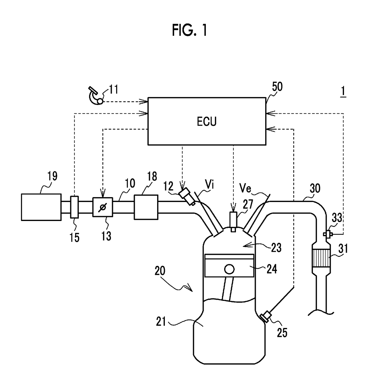
[0028]FIG. 1 is a schematic configuration view of an engine system 1. As shown in FIG. 1, the engine system 1 is equipped with an electronic control unit (an ECU) 50 that controls an engine 20. The ECU 50 is an exemplary control apparatus for an internal combustion engine. The engine 20 is an exemplary internal combustion engine in which an air-fuel mixture is burned in a combustion chamber 23 in a cylinder block 21 to move a piston 24 in a reciprocating manner. The engine 20 is an in-line four-cylinder gasoline engine, but is not limited thereto as long as it has a plurality of cylinders. For example, the engine 20 may be a diesel engine.

[0029]In a cylinder head of the engine 20, an intake valve Vi that opens / closes an intake port and an exhaust valve Ve that opens / closes an exhaust port are provided for each of the cylinders. Besides, an ignition plug 27 for igniting the air-fuel mixture in the combustion chamber 23 is attached to a top portion of the cylinder head, for each of th...


PUM


Abstract

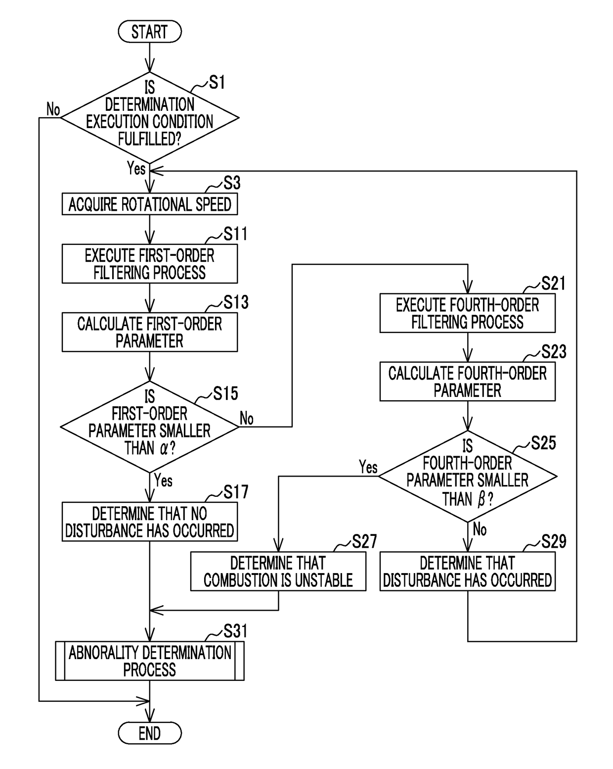
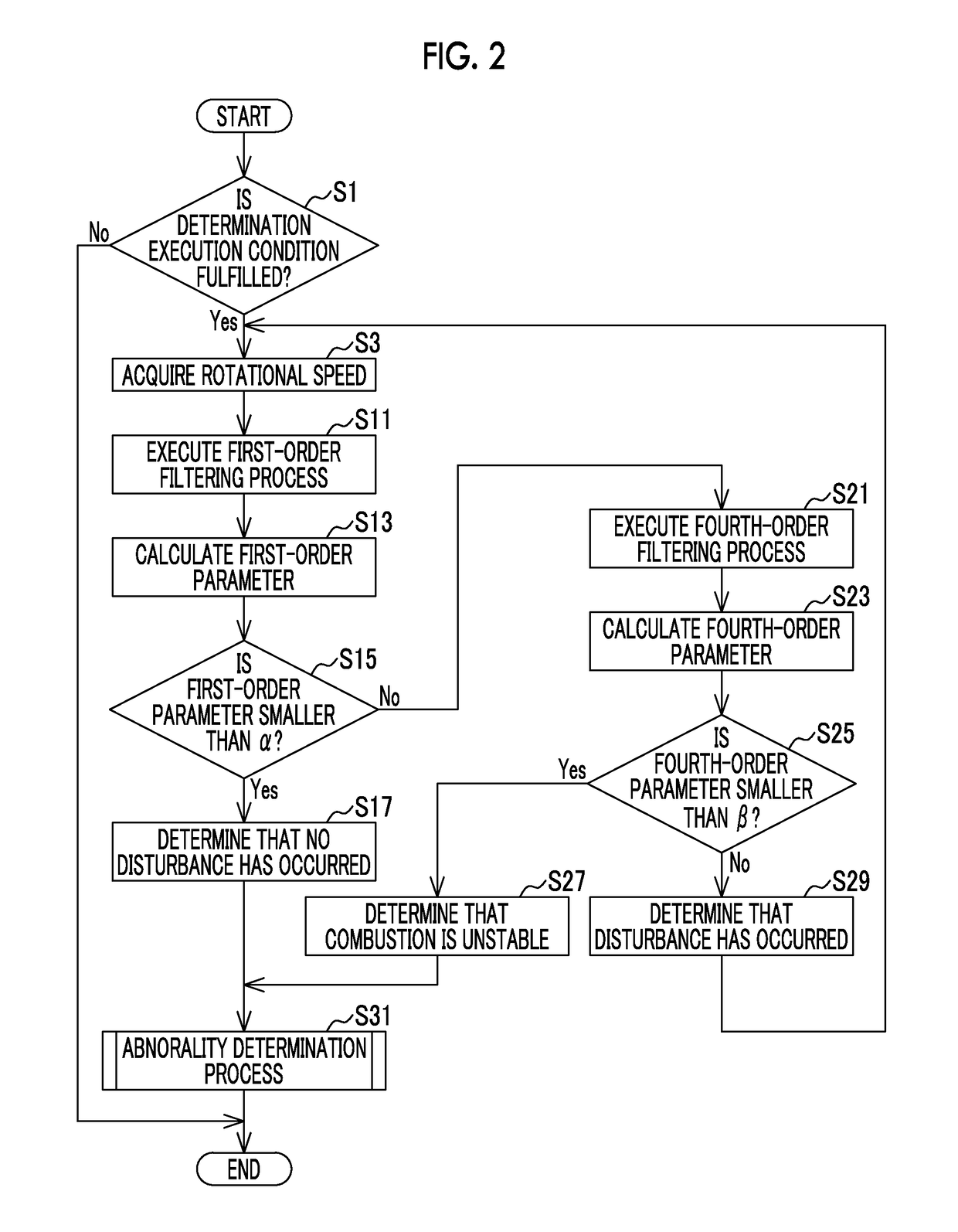
A control apparatus for an internal combustion engine (i) acquires a rotational speed signal correlated with a rotational speed of the internal combustion engine, (ii) extracts, from the acquired rotational speed signal, at least first-order and lower-order than the first-order components of the rotational speed signal, (iii) extracts, from the acquired rotational speed signal, at least an n-th-order component of the rotational speed signal, (iv) determines that no disturbance has occurred when a first-order parameter regarding a magnitude of an amplitude of the extracted first-order and lower-order than the first-order components is smaller than a first threshold, and (v) determines that a disturbance has occurred when the first-order parameter is equal to or larger than the first threshold and an n-th-order parameter regarding an amplitude of the extracted n-th-order component is equal to or larger than a second threshold.

Description

CROSS-REFERENCE TO RELATED APPLICATIONS[0001]The disclosure of Japanese Patent Application No. 2016-099009 filed on May 17, 2016 including the specification, drawings and abstract is incorporated herein by reference in its entirety.BACKGROUND1. Technical Field[0002]The disclosure relates to a control apparatus for an internal combustion engine.2. Description of Related Art[0003]In some cases, a disturbance may occur in an internal combustion engine as a result of running on a rough road. For example, Japanese Patent Application Publication No. 2006-194099 (JP 2006-194099 A) discloses an art of determining that a disturbance has occurred when a fluctuation rate of a rotational speed of an internal combustion engine is large. This fluctuation rate of the rotational speed is calculated as a difference between the last-detected rotational speed and the currently detected rotational speed.SUMMARY[0004]However, when the rotational speed of the internal combustion engine periodically fluct...

Claims


Application Information

Patent Timeline
Patent Type & Authority Patents(United States)
IPC IPC(8): F02D41/22F02D41/14F02D41/26G01M15/04F02D41/28
CPCF02D41/22F02D41/1498F02D41/26G01M15/046F02D2041/288F02D2200/101F02D2200/1012F02D2041/1432Y02T10/40
Inventor KITAOKA, TATSUKIMARUTA, SEITSURUOKA, KAZUKI
Owner TOYOTA JIDOSHA KK
Learn More