Uninterruptible power supply
a power supply and uninterruptible technology, applied in the direction of emergency power supply arrangements, circuit arrangements, electrical appliances, etc., can solve the problems of inability to supply ac voltage and difficulty in appropriately controlling the electromagnetic contactor
- Summary
- Abstract
- Description
- Claims
- Application Information
AI Technical Summary
Benefits of technology
Problems solved by technology
Method used
Image

Examples
embodiment
[0028]The structure of an uninterruptible power supply (UPS) 100 according to this embodiment is now described with reference to FIGS. 1 to 7.
[0029](Structure of Uninterruptible Power Supply)
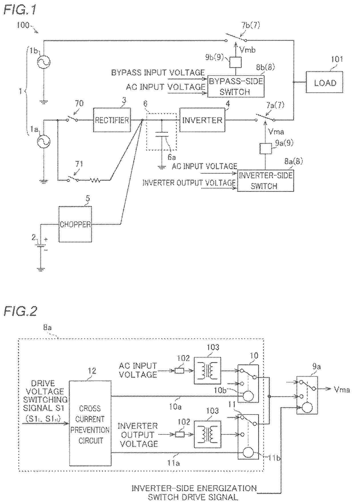
[0030]First, the schematic structure of the uninterruptible power supply 100 is described with reference to FIG. 1. As shown in FIG. 1, the uninterruptible power supply 100 includes an AC power source 1. The AC power source 1 includes a main AC input power source 1a and a bypass AC input power source 1b. The uninterruptible power supply 100 further includes a storage battery 2 that stores DC power. During the normal operation of the uninterruptible power supply 100, AC power output from the main AC input power source 1a is supplied to a load 101 connected to the uninterruptible power supply 100. Upon failure of the main AC input power source 1a, for example, a backup operation is performed in which the power stored in the storage battery 2 is supplied to the load 101. Furthermore, upon failure o...
modified examples
[0094]The embodiment disclosed this time must be considered as illustrative in all points and not restrictive. The range of the present invention is shown not by the above description of the embodiment but by the scope of claims for patent, and all modifications (modified examples) within the meaning and range equivalent to the scope of claims for patent are further included.
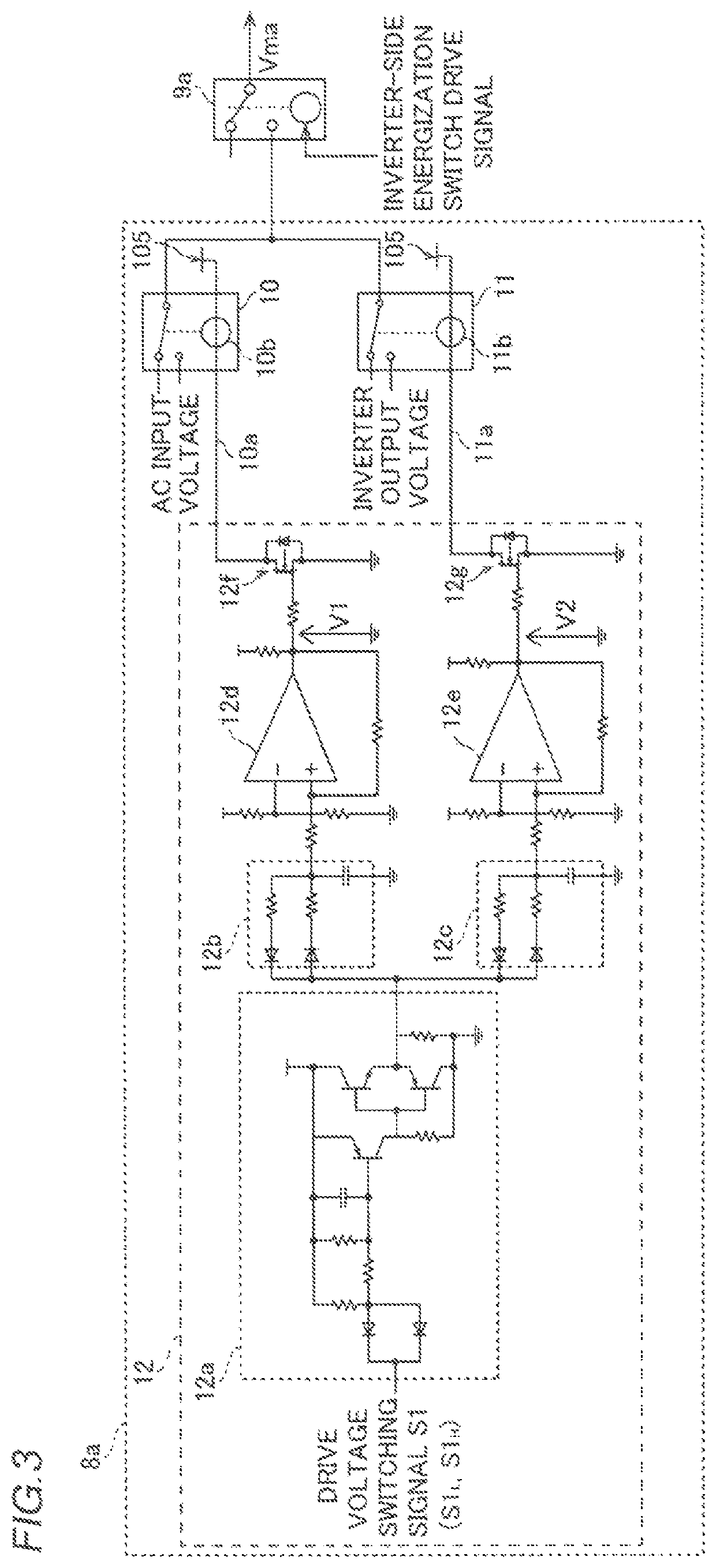
[0095]For example, while each of the first switching relay (switching relay 10 (13)) and the second switching relay (switching relay 11 (14)) is a mechanical relay in the aforementioned embodiment, the present invention is not restricted to this. For example, each of the first switching relay (switching relay 10 (13)) and the second switching relay (switching relay 11 (14)) may alternatively be a photo MOS relay (a relay driven based on light emission when excited).
[0096]While in the power converter-side switch (inverter-side switch 8a), the first switching relay (switching relay 10) is a b-contact relay, and th...
PUM
 Abstract
Description
Claims
Application Information
 - R&D Engineer
- R&D Manager
- IP Professional
- Industry Leading Data Capabilities
- Powerful AI technology
- Patent DNA Extraction
Browse by: Latest US Patents, China's latest patents, Technical Efficacy Thesaurus, Application Domain, Technology Topic.
© 2024 PatSnap. All rights reserved.Legal|Privacy policy|Modern Slavery Act Transparency Statement|Sitemap