Driving circuit for electrophoretic display device, electrophoretic display device, method for driving the same, and electronic apparatus

a technology of electrophoretic display device and driving circuit, which is applied in the direction of electric digital data processing, instruments, computing, etc., can solve the problems of deteriorating image contrast, image quality, image contrast,

Active Publication Date: 2012-01-03
E INK CORPORATION
View PDF4 Cites 2 Cited by
  • Summary
  • Abstract
  • Description
  • Claims
  • Application Information

AI Technical Summary

Benefits of technology

[0010]With this configuration, the electrophoretic element which has been driven by applying a voltage is likely to keep a state immediately after the driving of the electrophoretic element is stopped. Specifically, the electrophoretic particles included in the electrophoretic element are likely to stay positions where the electrophoretic particles are positioned after being moved by the driving. That is, for example, by stopping the supply of the first and second pixel potentials, the supply of the common potential, and the supply of the holding potential (that is, they are brought to high-impedance states) after the driving, power consumption is reduced.
[0012]With this configuration, in particular, as described above, the supply of the holding potential is stopped later than the supply of the other potentials. Therefore, occurrence of the kickback phenomenon can be reliably suppressed. Accordingly, the contrast, for example, is also prevented from being deteriorated, and consequently, quality of the displayed image is improved. Note that, the kickback phenomenon described above can be suppressed by controlling humidity of the electrophoretic element. However, since it is difficult to quantitatively control the humidity, an advantage may not reliably obtained. However, according to the aspect of the invention, by controlling a timing in which the supply of the holding potential is stopped, the kickback phenomenon is suppressed with a comparatively simple configuration.
[0014]The control unit may control the holding potential supplying unit so that the holding potential obtained in a period after the supply of the first and second pixel potentials and the supply of the common potential are stopped and before the supply of the holding potential is stopped is lower than the holding potential obtained when the supply of the first and second pixel potentials and the supply of the common potential are stopped.
[0016]When the electrophoretic element is driven in practical use (that is, while the first and second pixel potentials and the common potential are supplied), a comparatively high value is set to the holding potential so that the electrophoretic element is appropriately driven. However, when the supply of the first and second pixel potentials and the supply of the common potential are stopped, the driving of the electrophoretic element is stopped. Therefore, after the supply of the first and second pixel potentials and the supply of the common potential are stopped, it is not necessary to set a high value to the holding potential. Accordingly, for example, in a case where the holding potential is 15 V while the electrophoretic element is driven, and the holding potential is lowered to 5V after the supply of the first and second pixel potentials and the supply of the common potential are stopped, power consumption can be reduced in accordance with a difference between the holding potentials.
[0017]Note that a possibility of deterioration of the advantage in which the kickback phenomenon is reduced due to the holding potential lowered as described above is negligible. For example, in a case where the holding potential is lowered to a threshold voltage of the switching element included in the switching circuit (that is, a voltage corresponding to a threshold value of switching control), suppression of the kickback phenomenon is ensured.

Problems solved by technology

However, immediately after the pixel electrode and the common electrode are brought to high impedance states, a kickback phenomenon in which electrophoretic particles which have moved toward the pixel electrode and the common electrode are moved back toward the center (that is, in a direction in which the electrophoretic particles are moved away from the electrodes) occurs.
Therefore, for example, contrast of a displayed image is deteriorated due to the kickback phenomenon.
Accordingly, in the technique described above, there arises a technical problem in that image quality may be deteriorated since the pixel electrode and the common electrode are brought to the high impedance states.
When the kickback phenomenon occurs, contrast of a displayed image, for example, may be deteriorated.
However, since it is difficult to quantitatively control the humidity, an advantage may not reliably obtained.

Method used


Image

  • Driving circuit for electrophoretic display device, electrophoretic display device, method for driving the same, and electronic apparatus
  • Driving circuit for electrophoretic display device, electrophoretic display device, method for driving the same, and electronic apparatus
  • Driving circuit for electrophoretic display device, electrophoretic display device, method for driving the same, and electronic apparatus

Examples


Embodiment Construction

[0041]An Embodiment of the present invention will be described hereinafter with reference to the accompanying drawings.

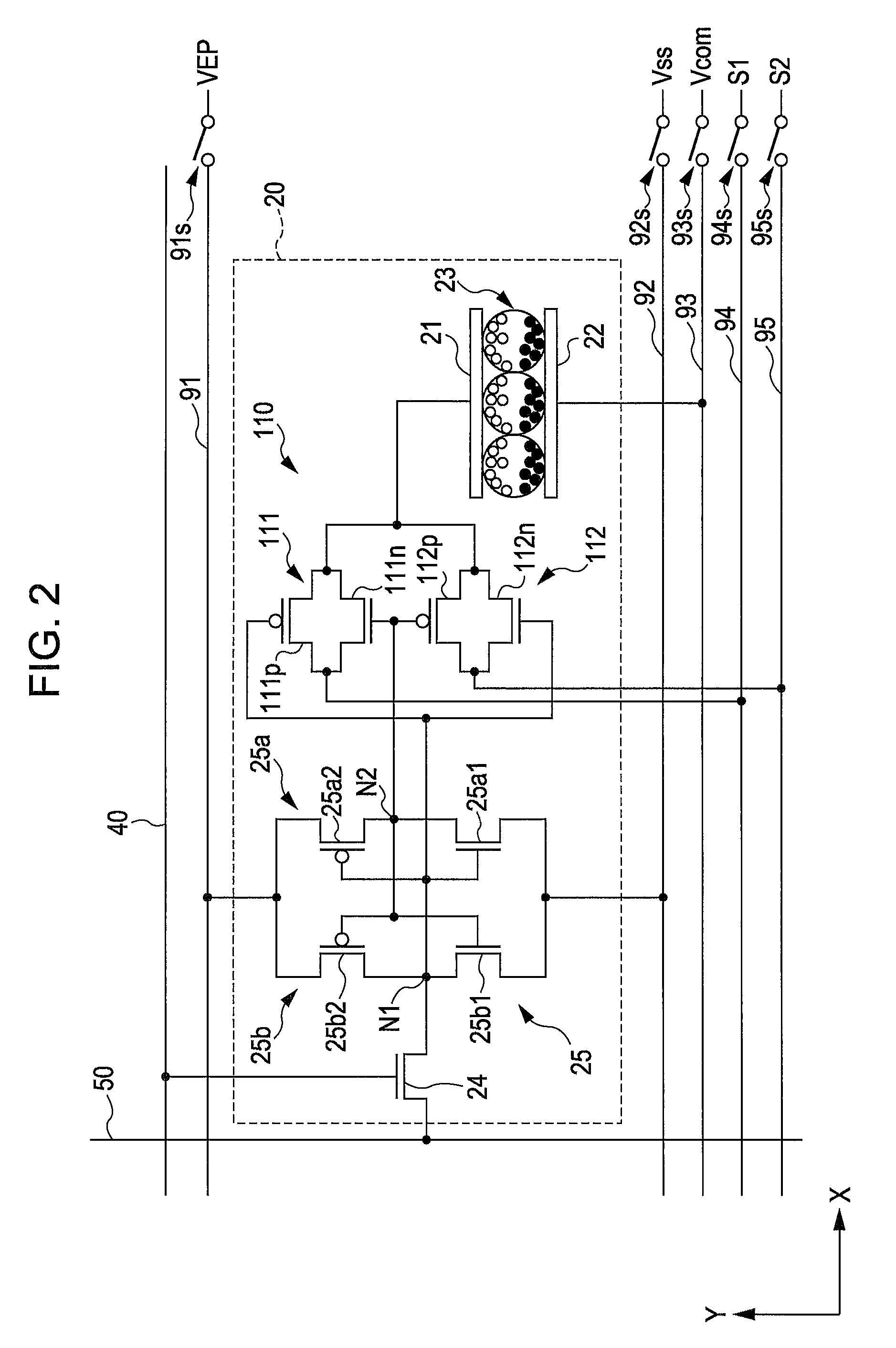
[0042]First, an entire configuration of an electrophoretic display device according to this embodiment will be described with reference to FIGS. 1 and 2. Note that, hereinafter, in addition to the configuration of the electrophoretic display device according to this embodiment, a configuration of a driving circuit for the electrophoretic display device according to this embodiment which is included in the electrophoretic display device will be described.

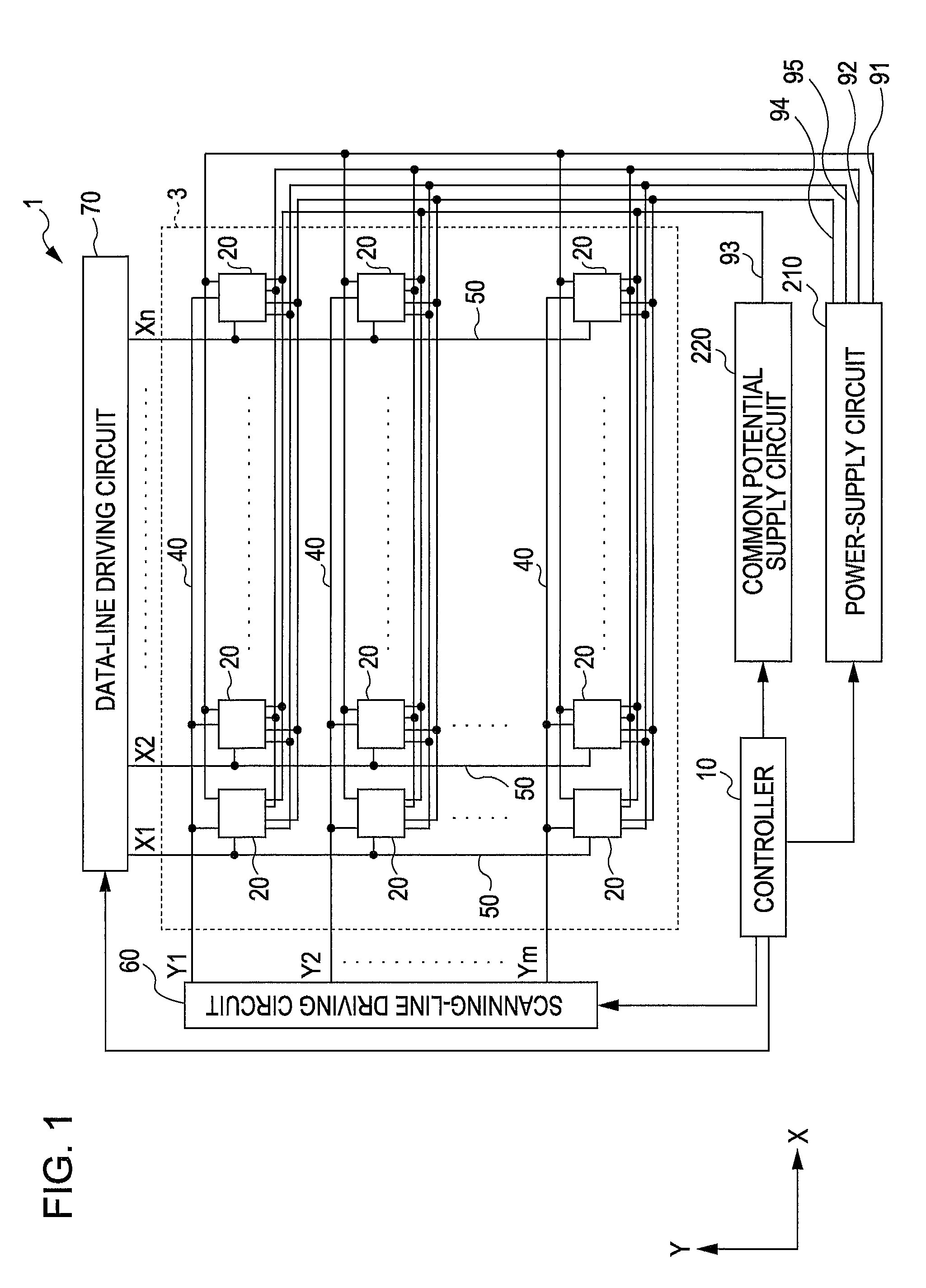
[0043]FIG. 1 is a block diagram illustrating the entire configuration of the electrophoretic display device according to this embodiment.

[0044]In FIG. 1, an electrophoretic display device 1 according to this embodiment includes a display unit 3, a controller 10, a scanning-line driving circuit 60, a data-line driving circuit 70, a power-supply circuit 210, and a common potential supply circuit 220.

[0045]The display u...


PUM


Abstract

In an electrophoretic device including a display including pixels with electrophoretic particles between pixel and common electrodes, a pixel-switching element, a memory holding an image signal from the pixel-switching element, and a switch connecting one of first and second control lines to the pixel electrode according to a signal output according to the image signal from the memory, a driving circuit includes a holding voltage unit supplying a holding voltage holding the image signal in the memory, a pixel potential unit supplying a first pixel potential to the first control line and a different second pixel potential to the second control line, a common potential unit supplying a common potential to the common electrode, and a control unit controlling the holding potential unit, the common potential unit, and the pixel potential unit to stop the holding potential after the first and second pixel potentials and common potential are stopped.

Description

BACKGROUND[0001]1. Technical Field[0002]The present invention relates to a driving circuit for an electrophoretic display device, the electrophoretic display device, a method for driving the electrophoretic display device, and an electronic apparatus.[0003]2. Related Art[0004]In general, electrophoretic display devices include display units which perform display operations using a plurality of pixels as described below. In each of the pixels, after an image signal is written to a memory circuit through a pixel switching element, a pixel electrode is driven using a pixel potential generated in accordance with the written image signal, and accordingly, a potential difference is generated between the pixel electrode and a common electrode. By this, an electrophoretic element between the pixel electrode and the common electrode is driven whereby the display operation is performed. Since the electrophoretic element has a characteristic in which once the electrophoresis element is driven,...

Claims


Application Information

Patent Timeline
Patent Type & Authority Patents(United States)
IPC IPC(8): G09G3/34
CPCG09G3/344G09G2300/0857G09G2300/0871
Inventor SAITO, HIDETOSHI
Owner E INK CORPORATION
Why Eureka
Try Eureka