Focus control device and method and imaging apparatus

Inactive Publication Date: 2016-06-16
HITACHI INFORMATION & CONTROL SOLUTIONS LTD
View PDF2 Cites 1 Cited by
  • Summary
  • Abstract
  • Description
  • Claims
  • Application Information

AI Technical Summary

Benefits of technology

[0017]According to an embodiment of the invention, it is possible to appropriately drive a focus lens in accordance with a priority level based on a contrast signal level calculated for each of a plurality of detection regions. For example, the controller preferentially stores subject

Problems solved by technology

Thus, in a known imaging apparatus, even if the focal point of the focus lens is determined by referring to the l

Method used


Image

  • Focus control device and method and imaging apparatus
  • Focus control device and method and imaging apparatus
  • Focus control device and method and imaging apparatus

Examples


Example

[0032]An imaging apparatus and a focus control device according to an embodiment of the invention will be described below with reference to the accompanying drawings.

[0033]In the specification and drawings, elements having substantially the same function or the same configuration are designated by like reference numerals, and an explanation thereof will be given only once.

(1) Configuration of Imaging Apparatus

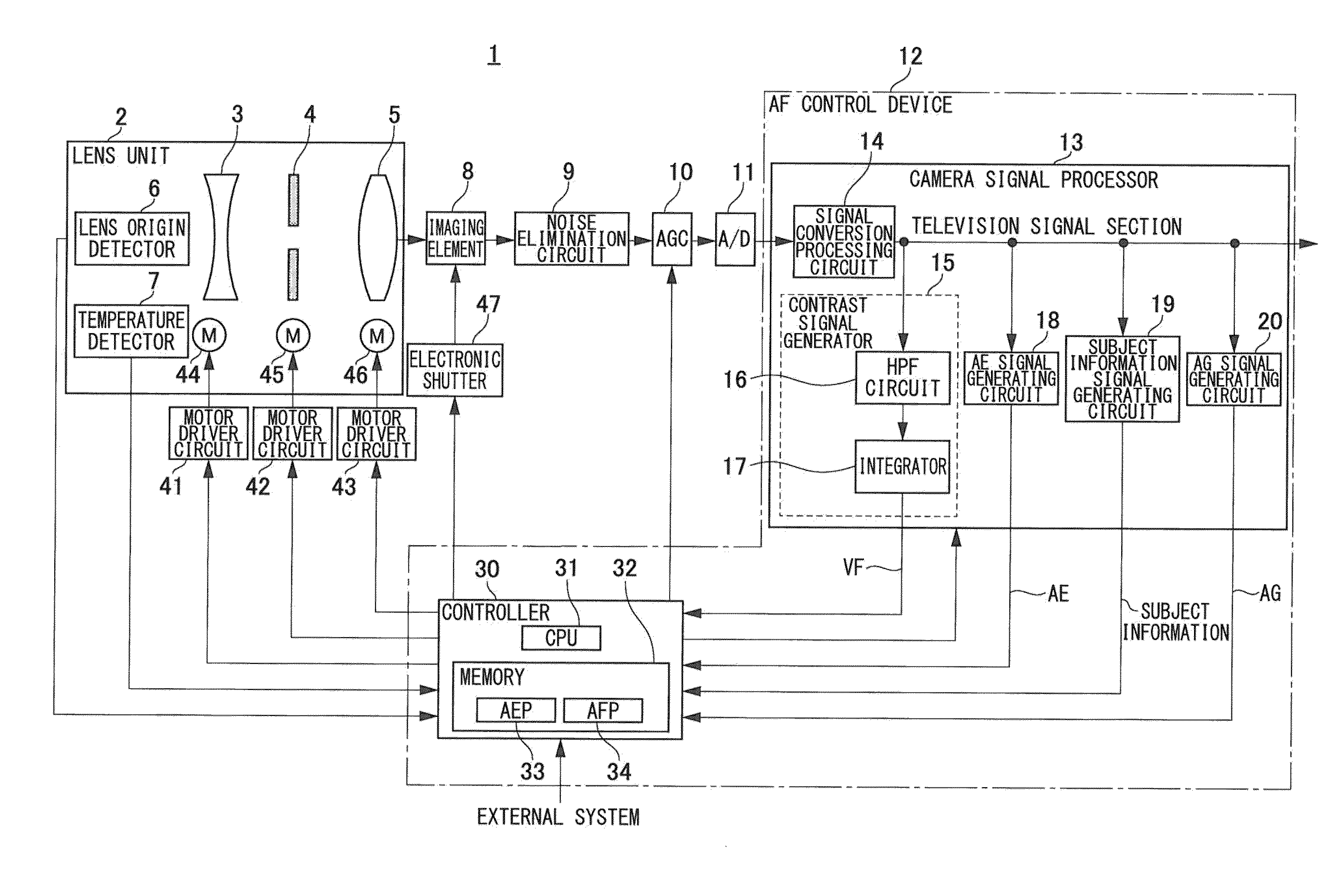
[0034]FIG. 1 is a block diagram illustrating the overall configuration of an imaging apparatus 1 of this embodiment.

[0035]The imaging apparatus 1 includes a lens unit 2, an imaging element 8, a noise elimination circuit 9, an auto gain control (AGC) circuit 10, an analog-to-digital (A / D) conversion circuit 11, and an auto focus (AF) control device 12. The imaging apparatus 1 also includes motor driver circuits 41 through 43 and an electronic shutter 47. The imaging apparatus 1 is used as, for example, a surveillance camera. However, the imaging apparatus 1 may be used as a pers...


PUM


Abstract

A controller sets a plurality of detection regions within an imaging area. The controller then compares a difference in a contrast signal level between a maximum contrast signal level and a minimum contrast signal level calculated from among contrast signal levels of contrast signals generated for the plurality of detection regions with a level difference threshold. The controller then sets a priority level in subject information concerning a subject on the basis of a comparison result. The controller then stores the subject information in a storage unit in accordance with the priority level set in the subject information. The controller then drives a focus lens on the basis of the subject information read from the storage unit so as to bring the focus lens into focus.

Description

BACKGROUND OF THE INVENTION[0001]1. Field of the Invention[0002]The present invention relates to a focus control device and method and an imaging apparatus for performing auto focus control for a subject.[0003]2. Description of the Related Art[0004]Hitherto, an auto focus (AF) function of automatically adjusting the focus of a lens is provided in many imaging apparatuses provided with video recorders, such as surveillance cameras and digital versatile disc (DVD) cameras. One of the focusing methods used in an AF function is a contrast AF method in which the focus is adjusted by detecting a position of a contrast signal of an imaging subject at which the amplitude is maximized.[0005]In an imaging apparatus, by shifting a focus lens in the optical axis direction thereof, an imaging subject is set in the focusing state or the non-focusing state, and in accordance with the movement of the focus lens, the amplitude of a contrast signal of the imaging subject also changes. Thus, in a basi...

Claims


Application Information

Patent Timeline
IPC IPC(8): H04N5/232G02B7/09
CPCH04N5/23212G02B7/09H04N5/23287G02B7/102H04N23/673
Inventor UMEZAWA, IORIONO, HIDEHARUNISHIGUCHI, TOMOAKIYOKOYAMA, TOSHIYUKIINOKUCHI, TOSHIFUMISHIROTA, YUKITOSHI
Owner HITACHI INFORMATION & CONTROL SOLUTIONS LTD
Why Eureka
Try Eureka