Spray Guide

Inactive Publication Date: 2009-03-05
POTTER TERRY
View PDF4 Cites 2 Cited by
  • Summary
  • Abstract
  • Description
  • Claims
  • Application Information

AI Technical Summary

Benefits of technology

[0008]Certain embodiments of the present invention provide a paint spray guide tha

Problems solved by technology

The conventional way of painting edges, especially wall edges near a ceiling is a very tedious, arduous process.
This dramatically increases the time it takes a painter to paint, resulting in a much lower productively and earning po

Method used


Image

  • Spray Guide
  • Spray Guide
  • Spray Guide

Examples


Example

REFERENCE NUMERALS UTILIZED IN THE DRAWINGS

[0016]10 paint spray guide[0017]12 swivel angle head[0018]14 spray wand[0019]16 spray nozzle[0020]18 arm of paint spray guide 10[0021]20 first end of arm 18[0022]22 second end of arm 18[0023]24 removably attaching mechanism of paint spray guide 10[0024]26 wheel of paint spray guide 10[0025]28 rotatably connecting mechanism of paint spray guide 10[0026]30 edge of wheel 26[0027]32 cornerjoint[0028]34 wall[0029]36 ceiling[0030]38 Paint[0031]40 C-clamp member of removably attaching mechanism 24[0032]42 thumbscrew of removably attaching mechanism 24[0033]44 aperture in second end 22 of arm 18[0034]46 stub shaft of rotatably connecting mechanism 28[0035]48 fastener of rotatably connecting mechanism 28[0036]50 curved bumper member of paint spray guide 10[0037]60 spray guide[0038]61 spray assembly[0039]62 wheel[0040]64 arm[0041]66 spray nozzle[0042]67 clamp[0043]68 wand[0044]69 hinge

DETAILED DESCRIPTION

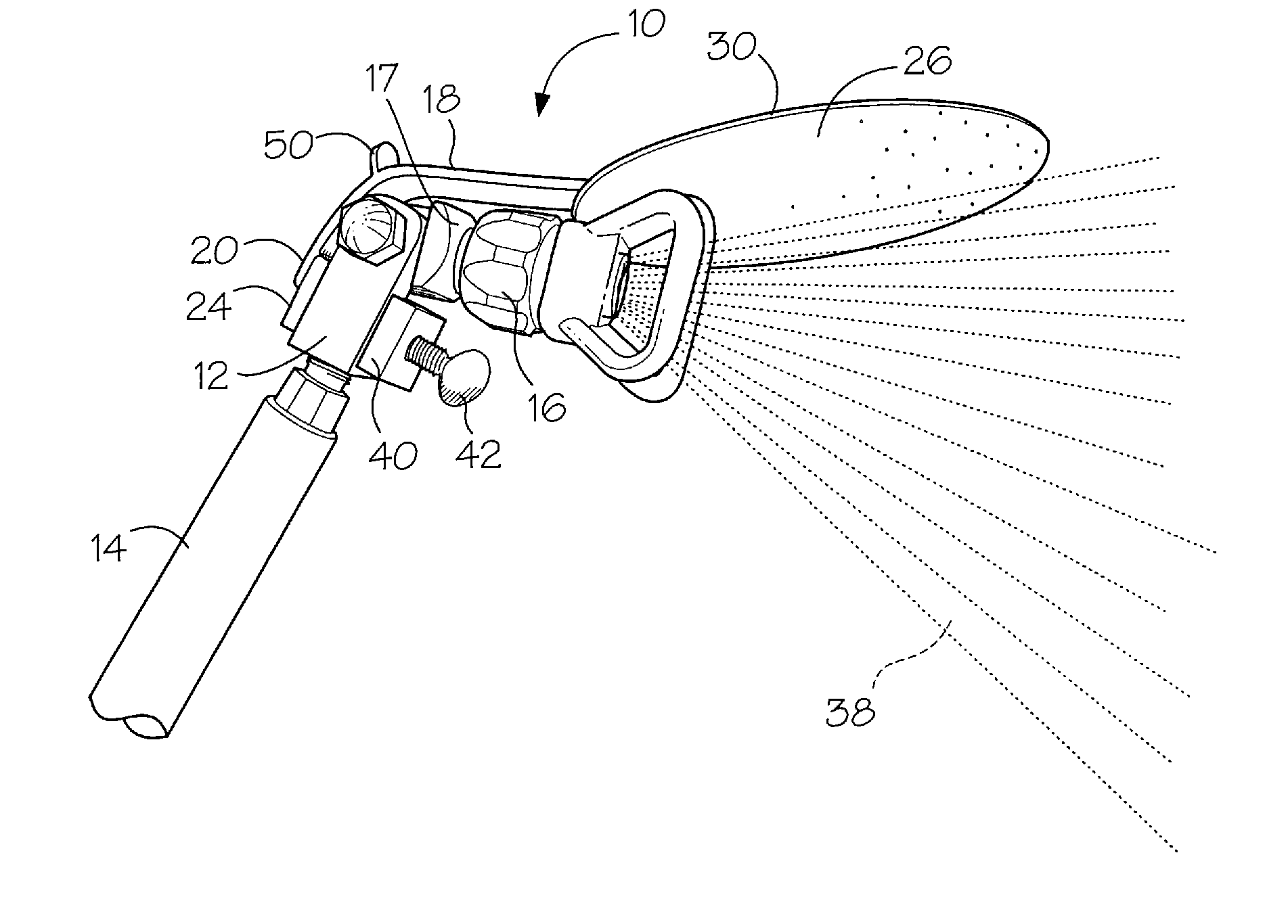
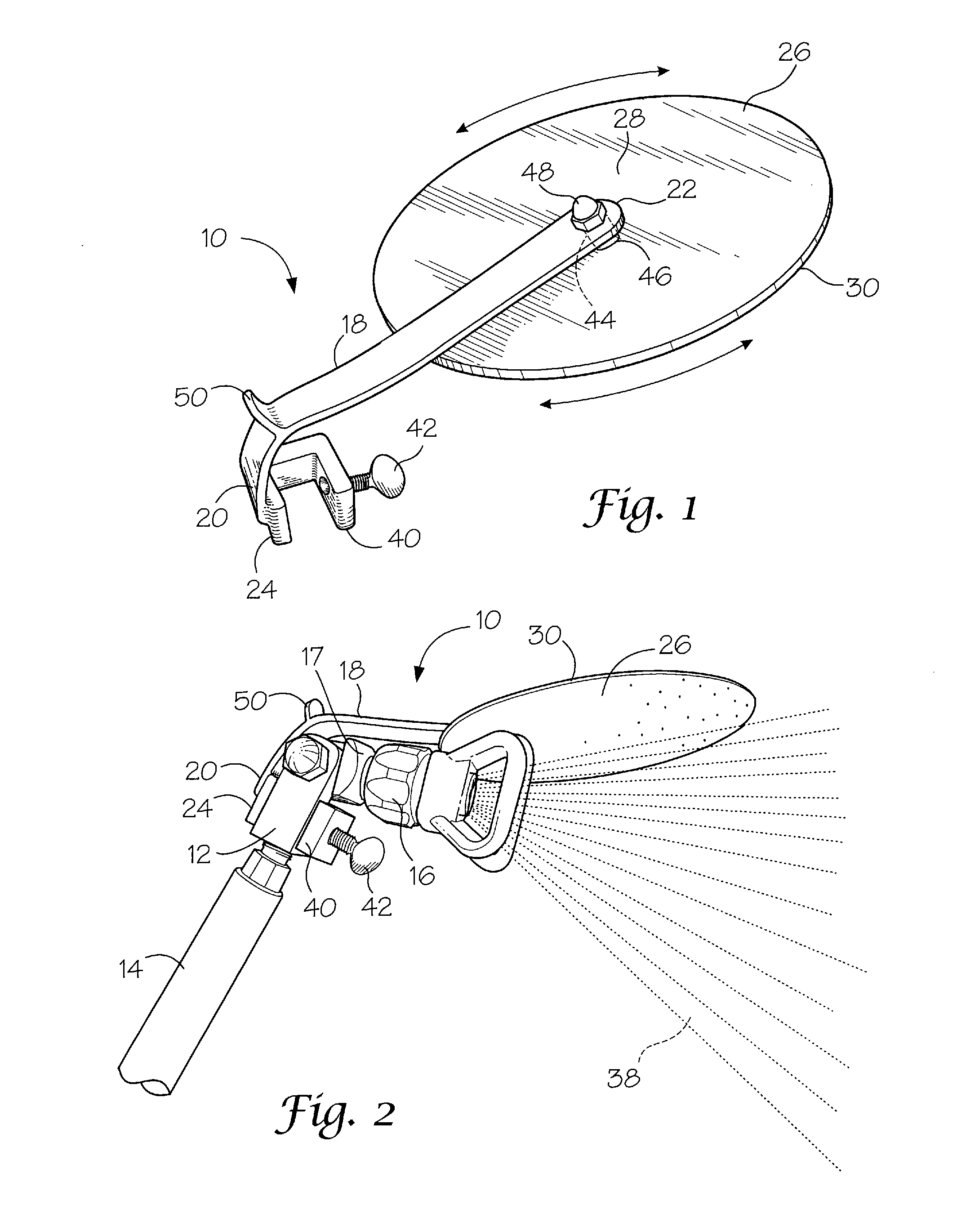
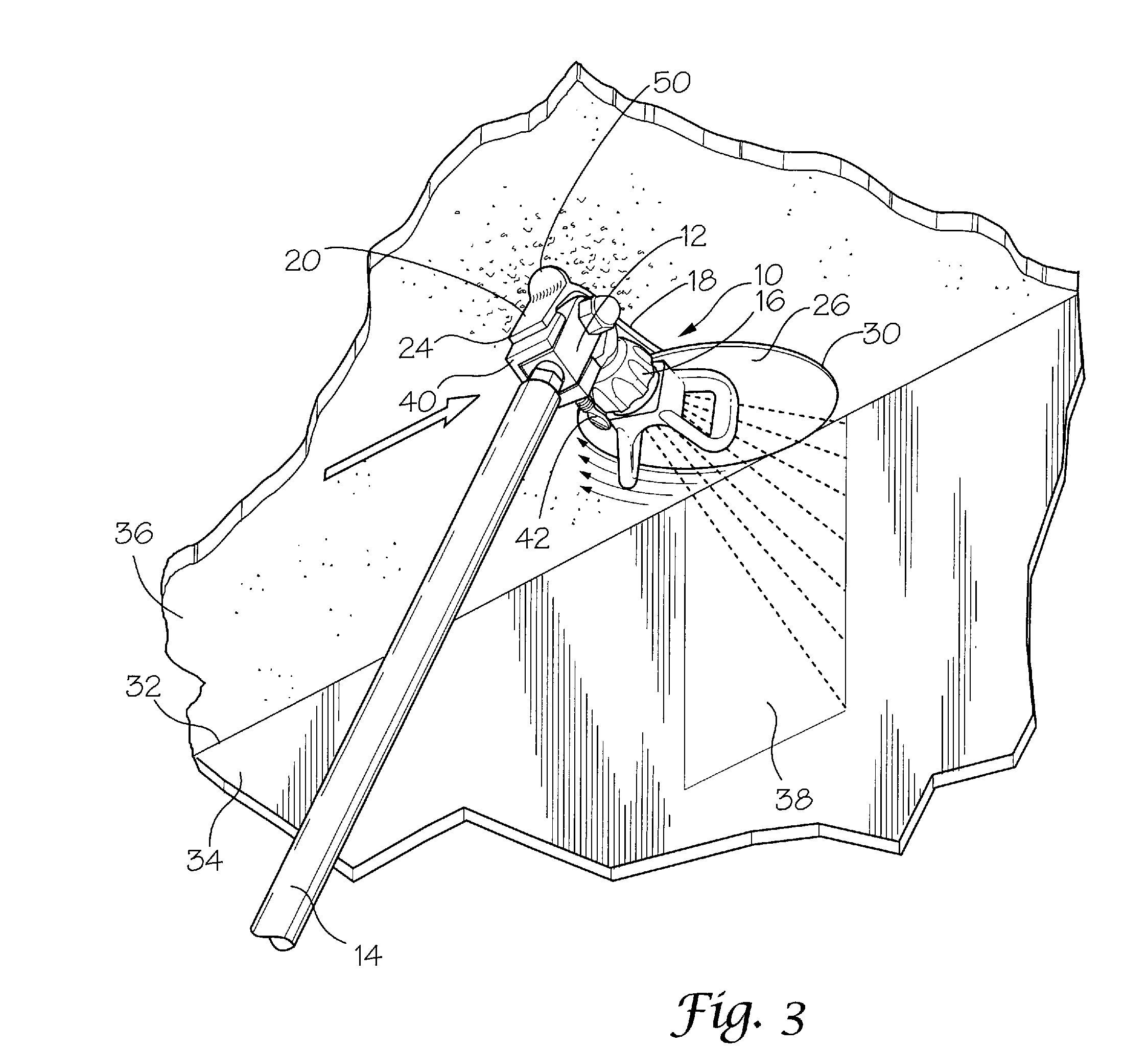
[0045]Referring now to the figures, in which l...


PUM


Abstract

A spray guide is disclosed herein for implementation with a spray assembly comprising a spray wand and a spray nozzle. The spray guide includes an arm having a first end and a second end. A mechanism is used for removably attaching the first end of the arm to the swivel angle head, so that the arm will extend over the swivel angle head and the spray nozzle. A wheel is also provided. Another mechanism is provided for rotatably connecting the wheel to the second end of the arm. When an edge of the wheel is placed in a corner joint between a wall and a ceiling and the spray wand manually moved therealong, the wheel will rotate in the corner joint to allow paint to be evenly sprayed from the spray nozzle onto an area of the wall adjacent to the ceiling.

Description

FIELD OF THE INVENTION [0001]The present invention relates to a paint sprayer accessory, and more particularly, paint spray guide.BACKGROUND [0002]The conventional way of painting edges, especially wall edges near a ceiling is a very tedious, arduous process. It requires that a painter use a paint sprayer in one hand and a long handle paint shield in another hand. The painter must climb up a ladder with these two items in his hands, and paint a wall that he can reasonably reach. Then the painter must climb down the ladder, move it and climb back up to paint another region of the wall. This dramatically increases the time it takes a painter to paint, resulting in a much lower productively and earning potential for the painter.[0003]U.S. Pat. No. 4,085,703 issued on Apr. 25, 1978 to Glowacki teaches a spray painting shield that includes a flat reinforcing member attached to an elongate handle. The shield permits a painter or his assistant to support the shield while keeping his arms a...

Claims


Application Information

Patent Timeline
IPC IPC(8): B05B3/00
CPCB05B1/267B05B15/0443B05B15/0437B05B12/34B05B12/36B05B12/22
Inventor POTTER, TERRY
Owner POTTER TERRY
Why Eureka
Try Eureka