Charging installation of a metallurgical reactor

a metallurgical reactor and charging installation technology, applied in the direction of furnaces, furnace cooling arrangements, furnace types, etc., can solve the problems of severe operation of the cooling assembly, and achieve the effect of facilitating the installation and maintenance of the heat protection shield

Active Publication Date: 2020-09-08
PAUL WURTH SA
View PDF32 Cites 0 Cited by
  • Summary
  • Abstract
  • Description
  • Claims
  • Application Information

AI Technical Summary

Benefits of technology

[0003]The disclosure facilitates the installation and maintenance of a heat protection shield in a charging installation of a metallurgical reactor. A charging installation, a cooling assembly, and a cooling panel are provided.

Problems solved by technology

As mentioned before, the cooling assembly usually operates under severe conditions and still has to function perfectly to protect other parts of the charging installation.

Method used


Image

  • Charging installation of a metallurgical reactor
  • Charging installation of a metallurgical reactor

Examples


Embodiment Construction

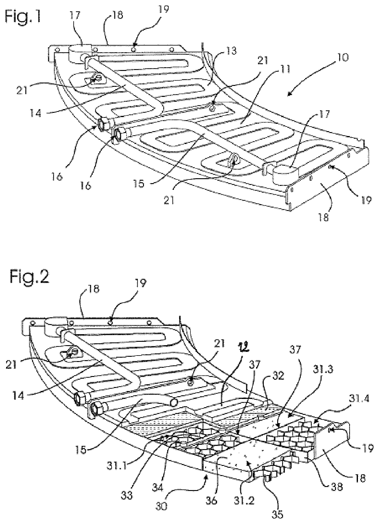
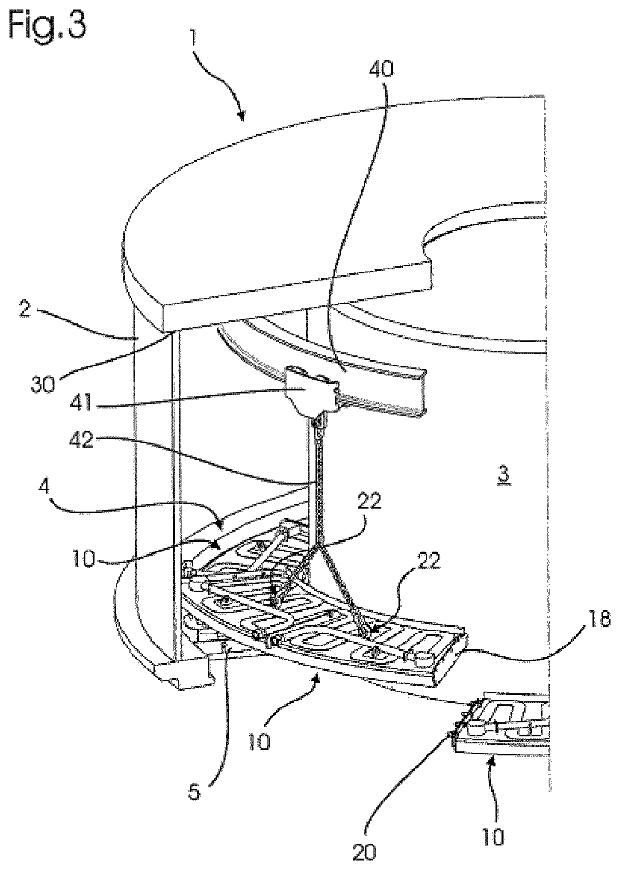
[0031]FIG. 1 shows a perspective view of a cooling panel 10 according to the present invention. The cooling panel 10 is part of a cooling assembly 4 which protects the annular bottom surface of the casing 2, which is part of a charging installation 1 for a metallurgical reactor. Due to the annular shape of the surface to be protected, the panel 10 is generally arc-shaped. Its general configuration is relatively flat and it comprises a planar base plate 11, which is made of steel. As can be seen in the cutaway view in FIG. 2, a coolant channel 12 has been machined into the surface of the base plate 11. To provide a fluid-tight seal of the coolant channel 12, it is closed on the upper side by a cover plate 13, which has the same meandering structure as the coolant channel 12 itself. The cover plate, which itself is made of steel, is connected to the base plate 11 by welding. The coolant channel 12 is connected to a supply pipe 14 and a drain pipe 15. These pipes 14, 15 are conventiona...


PUM

PropertyMeasurementUnit
temperaturesaaaaaaaaaa
shapeaaaaaaaaaa
operating temperaturesaaaaaaaaaa

Abstract

The invention relates to a charging installation (1) of a metallurgical reactor, with a cooling assembly (4) disposed for cooling a reactor side of the charging installation (1). In order to facilitate the installation and maintenance of a heat protection shield in a charging installation of a metallurgical reactor, the cooling assembly (4) comprises a plurality of cooling panels (10), each cooling panel (10) comprising at least one coolant channel (12). The channel (12) is formed as a groove in the base plate (11), which groove is covered by a cover plate (13) mounted on the base plate (11).

Description

TECHNICAL FIELD[0001]The invention relates to a charging installation of a metallurgical reactor. It further relates to a cooling assembly of such a charging installation and a cooling panel for such a cooling assembly.BACKGROUND ART[0002]Metallurgical reactors are well known in the art. These reactors are typically gravity-fed from above by a charging installation, which in turn may be fed with bulk material from intermediate hoppers. One type of charging installation is disclosed in international application WO 2012 / 016902 A1. Here, the material is fed through a feeder spout, which is positioned above the inlet of a distribution chute. The chute is mounted on a rotatable tubular support, in which the feeder spout is disposed. To provide for a two-dimensional mobility of the chute, it is also tiltable relative to the support by shafts connected to a gear assembly. The gear assembly is positioned inside a gearbox formed by the support and a stationary casing on which the support is ...

Claims


Application Information

Patent Timeline
Patent Type & Authority Patents(United States)
IPC IPC(8): F27B3/24F27D1/00F27D1/12F27B3/18F27B1/20
CPCF27B1/20F27B3/18F27D1/12F27B3/24F27D1/0033
Inventor TOCKERT, PAULPELLEGRINO, ERNESTOHIENTGEN, RENÉ
Owner PAUL WURTH SA
Why Eureka
Try Eureka