System for liquid leak control and/or air flotation system

a liquid leakage control and air flotation technology, applied in the field of applications, can solve the problems of liquid leakage, damage, and damage to building structures and properties, and achieve the effects of preventing “creeping” of the appliance, facilitating installation and maintenance of the supported appliance, and improving the ergonomic use of the applian

Inactive Publication Date: 2013-08-15
CHILCOAT EDWARD A
View PDF10 Cites 0 Cited by
  • Summary
  • Abstract
  • Description
  • Claims
  • Application Information

AI Technical Summary

Benefits of technology

[0017]This invention incorporates the functions of liquid leak control collection and disposal into an appliance elevating pedestal into a single device. It provides liquid control in both passive and active manners. For passive control, the invention directs leaking liquids to the incorporated retention sump out of contact with the appliance. The collected liquid may be retained or discharged by means of an incorporated gravity drain. The invention provides active control by supplying space for the incorporation of a pump for discharging collected liquids to an elevated or distant plumbing system such as a standpipe. The invention eliminates the need for lifting the full weight of the appliance. The invention does not need to be mounted to the appliance eliminating much of the handling requirements for the installation of a pedestal. It facilitates installation and maintenance of the supported appliance from the front of the invention by one person. It provides for mounting to the supporting surface to prevent “creeping” of the appliance by inertia generated by earthquake or “out of balance” conditions during an appliance operating cycle. The invention elevates the supported appliance for improved ergonomic use of the appliance by an operator and compliance with ADA.
[0020]The present invention also includes an appliance floatation system that can be activated by a technician or other person to raise the appliance itself or an appliance pedestal supporting an appliance from its contact with the supporting surface such that the technician or other person can easily move the appliance from one location to another.

Problems solved by technology

Damage to building structures and property can result from liquid leakage due to failures within a liquid filled, liquid handling, or liquid generating appliances.
The damage can be quite significant especially in multi-family and multi-level structures.
This risk of significant damage has also spurred the creation of building codes that require the installation of some system of control to prevent such damage in the event of liquid control failure within a piece of equipment.
1. Machines must be lifted in or out of pan for installation and service or the pan must be of a multi-component configuration that must be assembled and sealed after the appliance has been put into position.
2. The shallow pans have limited retention capacity.
3. When a pan of this configuration is deepened to increase water retention capacity, the machine sits in the reservoir and can be damaged due to corrosion and electrically energized components are exposed to liquids creating potentially dangerous conditions.
4. The limited reservoir does not support a method for pumping liquids to an elevated drain or standpipe.
5. It does not address raising the appliance for improved ergonomic benefits.
This style of pan typically requires the installer or service technician to lift the appliance vertically in or out of the pan during installation or service of the equipment frequently resulting in damage to the pan or strain and injury to the service technician or both.
Many times it requires two installers or service technicians to lift the machine in or out of such a pan resulting in higher installation and repair costs.
Equipment installations in confined closet type installations are extremely difficult because technicians must lift the appliance from multiple sides where there is limited or no access.
Increasing height of the perimeter wall can increase the liquid retention volume but exacerbate the aforementioned installation and maintenance issues.
Allowing these increased liquid levels can also increase direct damage to the appliance itself and create safety hazards such as liquid levels coming into contact with energized parts or submerging fuel gas supply systems.
Collection pan systems disclosed in the present art do not accommodate a necessary sump or volume area for the incorporation of a pump system to positively discharge liquids collected by the system to existing plumbing systems regardless of distance or elevation.
The current art in elevating pedestals, such as those used to elevate laundry appliances, provide no means of leak control.
One of the common problems with appliances today is in the lack of mobility, that is, whether the appliance is a dishwasher, clothes washer, dryer or the like, the appliance may be located among cabinets, other appliances, possible in a small room where the ability to access the appliance for moving the same is limited.
The problem is particularly acute during repairing the appliance by technicians who normally must move the appliance away from a wall or other barrier to obtain sufficient access to the appliance in order to carry out some repair thereof.
With many appliances, it requires two technicians to move the appliance; therefore the cost of that repair is increased by the need to have an additional technician on the scene to manipulate the appliance into and out of a particular location.

Method used


Image

  • System for liquid leak control and/or air flotation system
  • System for liquid leak control and/or air flotation system
  • System for liquid leak control and/or air flotation system

Examples


Embodiment Construction

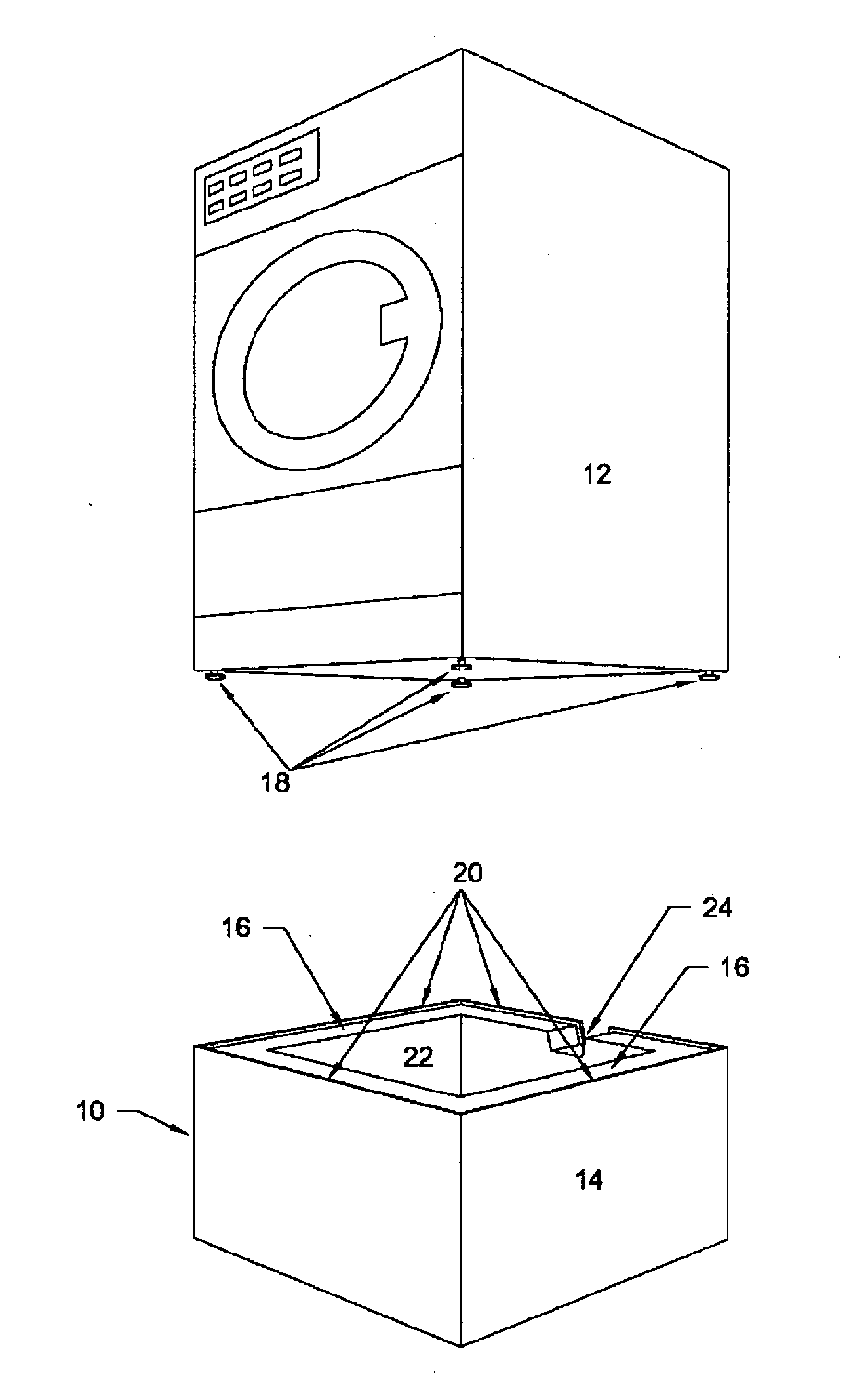
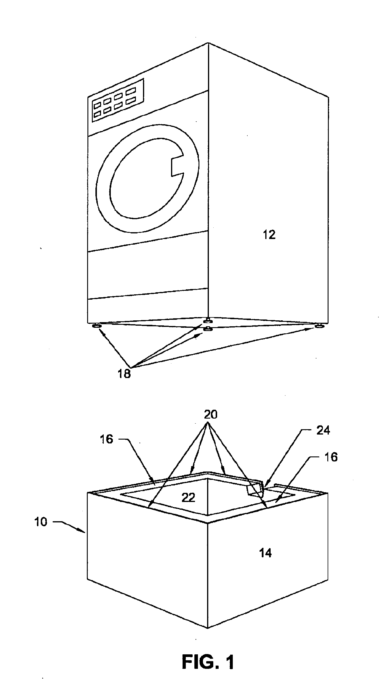
[0050]Turning first to FIG. 1, there is shown an exploded view illustrating the appliance pedestal 10 of the present invention in position to support an appliance 12. The appliance 12 is of the type that uses and thus contains a quantity of liquid, typically water, in carrying out its function and may be a clothes washer. As can be seen, the appliance pedestal 10 comprises a housing 14 that is of a three dimensional rectilinear shape and in the illustrated embodiment, the housing 14 is cubical in shape.

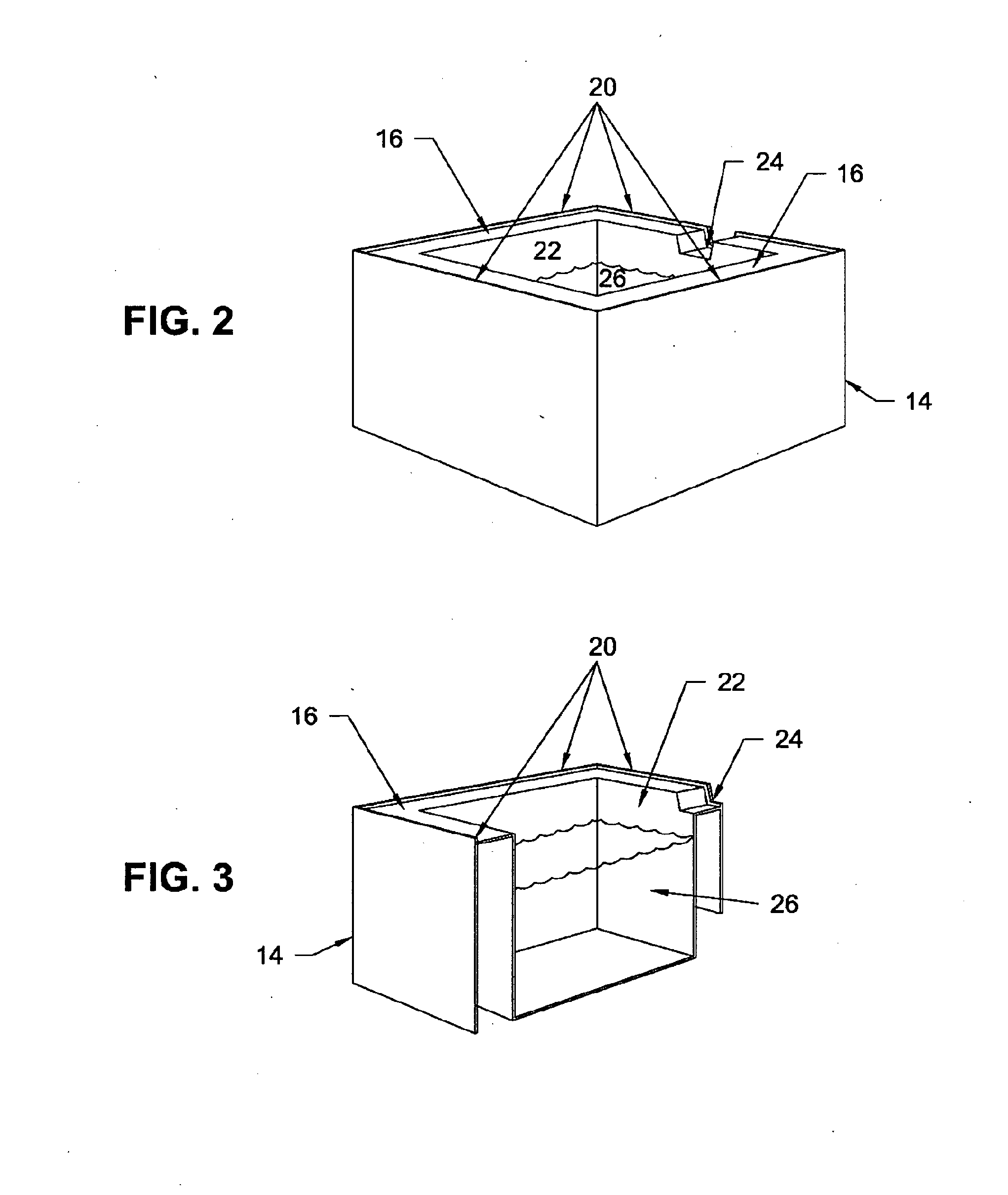
[0051]The upper surface of the housing 14 is comprised of perimeter rails 16 that support the feet 18 of the appliance 12 supported atop of the housing 14. The perimeter rails 16 have a lip 20 to direct liquids leaking from the supported appliance 12 to the interior and to prevent the appliance 12 from slipping off the perimeter rails 16. The perimeter rails 16 and lip 20 channel liquids to a liquid-tight sump 22 located in the interior of the housing 14. The liquid-tight sump 22 is s...


PUM

PropertyMeasurementUnit
perimeteraaaaaaaaaa
gravityaaaaaaaaaa
movementaaaaaaaaaa

Abstract

Appliance pedestal that contains liquid leaks due to condensation, overflow, or system failure originating from the supported liquid filled or handling appliance, provides for multiple methods of discharge of collected liquids, and reduces installation and maintenance requirements and their associated hazards and provides an improved ergonomic operating position for the appliance operator. There is also a system to facilitate the movement of an appliance or pedestal supporting an appliance along a supporting surface. That system includes a chamber located at or proximate to the bottom of the appliance or pedestal having a plurality of openings formed therein. The chamber is pressurized to create a plurality of jets where fluid passes outwardly from the jets toward the supporting surface. The jets raise or float the appliance or the pedestal raising the appliance upwardly off of the supporting surface and allows the easy movement of the appliance along that supporting surface.

Description

FIELD OF THE INVENTION[0001]The present invention relates to the field of appliances and, more particularly, to a system wherein the appliance includes an elevating and storage pedestal for the containment and proper discharge of liquids due to plumbing failure, seal failure, or mechanical failure within a liquid filled appliance such as, but not limited to, clothes washing machines, condensing clothes dryers, water heaters, dishwashers, refrigerators, icemakers, and similar devices and to an air flotation system for facilitating the moving of an appliance alone or an appliance located on a storage pedestal.BACKGROUND OF THE INVENTION[0002]Damage to building structures and property can result from liquid leakage due to failures within a liquid filled, liquid handling, or liquid generating appliances. The damage can be quite significant especially in multi-family and multi-level structures. This risk of significant damage has also spurred the creation of building codes that require t...

Claims


Application Information

Patent Timeline
Patent Type & Authority Applications(United States)
IPC IPC(8): F17D5/02
CPCA47L15/4212D06F39/081Y10T29/49826F17D5/02D06F39/125D06F39/085Y10T137/0402Y10T137/5835Y10T137/8158Y10T137/86043Y10T137/86067A47L15/4223F17D1/14
Inventor CHILCOAT, EDWARD A.
Owner CHILCOAT EDWARD A
Why Eureka
Try Eureka