Control panel and image forming apparatus
a technology of control panel and image forming apparatus, which is applied in the direction of electrographic process apparatus, instruments, computing, etc., can solve the problems of erroneous operation of information processing apparatus, difficult to see or operate the control panel depending on the person, and relative large apparatus such as image forming apparatus,
- Summary
- Abstract
- Description
- Claims
- Application Information
AI Technical Summary
Benefits of technology
Problems solved by technology
Method used
Image

Examples
first embodiment
[0057]Next, a hardware configuration of the image forming apparatus 1000 will be described with reference to FIG. 7.
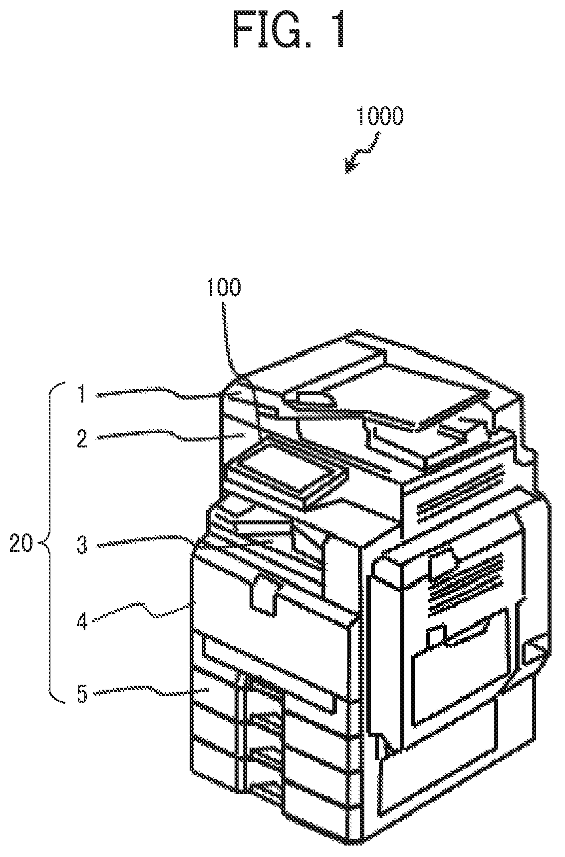
[0058]The image forming apparatus 1000 according to this embodiment is a so-called multifunction peripheral / product / printer (MFP) having multi functions such as a copier function, a fax function, a printer function, a scanner function, and a function of storing or distributing data of an input image (image read by using the scanner function or image input by using the printer or fax function). Note that various types of image data to be processed by the image forming apparatus 1000 in this embodiment include data of text information alone without images.
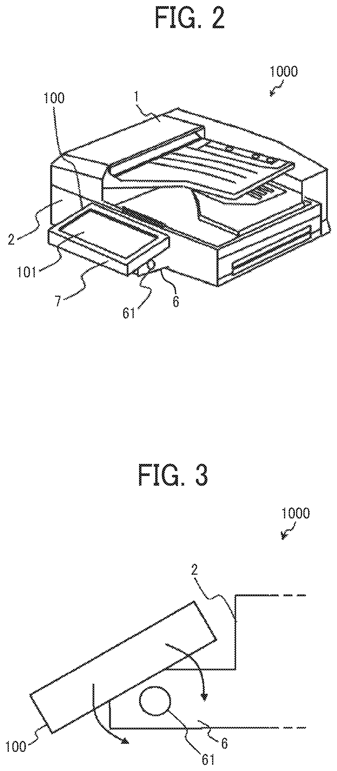
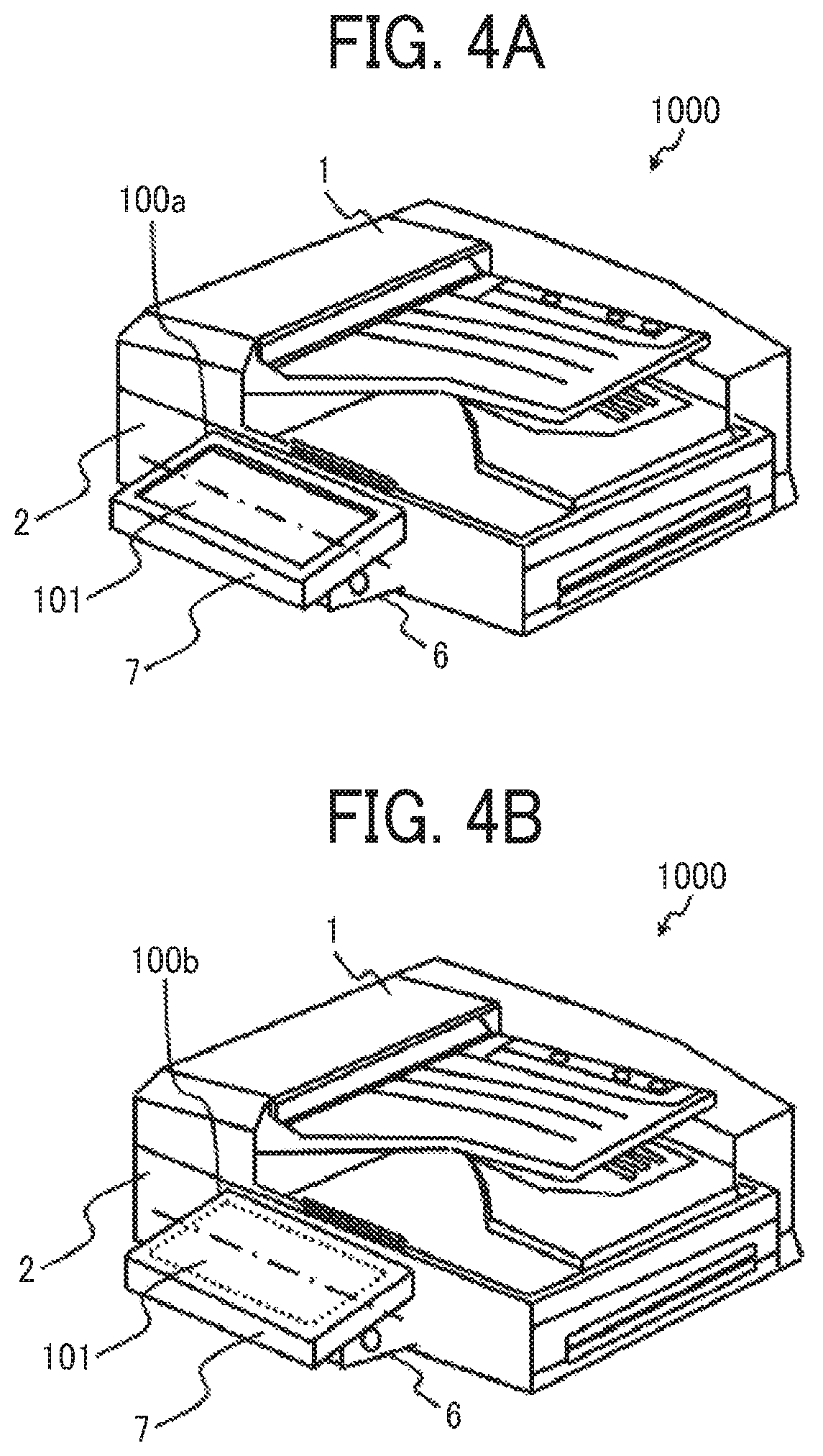
[0059]As illustrated in FIG. 7, the image forming apparatus 1000 includes an operation device 10 that receives an instruction given by a user operation and the main device 20 that works to implement various functions such as the copier function, the fax function, and the scanner function in response to an instruction f...
second embodiment
[0130]FIG. 17 illustrates a hardware configuration of the image forming apparatus 1000 according to a The operation device 10 illustrated in FIG. 17 includes a tilt sensor 8 that is a sensor for sensing the tilt of the control panel 100 relative to the main device 20. The tilt sensor 8 is mutually connected to the other components of the control panel 100 via the system bus 17. The components other than the tilt sensor 8 in FIG. 17 are the same as those in FIG. 7 and are not repeatedly described.
[0131]FIG. 18 illustrates a structure of the tilt sensor 8.
[0132]As illustrated in FIG. 18, in the tilt changing section 6, a protrusion 62 is provided at a part of the shaft section 61. The protrusion 62 rotates along with the rotation of the shaft section 61. In addition, the tilt sensor 8 including a plurality of sensing sections is provided at a part of the main device 20, the part not moving along with the tilt change of the control panel 100. Any sensor may be used as each of the sens...
PUM
 Abstract
Description
Claims
Application Information