
Probe insertion system

a robotic probe and probe technology, applied in the field of automatic robotic probe insertion, can solve the problems of reducing the efficiency of visual inspection, reducing the quality of borescope inspection, and measuring error,

Active Publication Date: 2020-09-15
GENERAL ELECTRIC CO
View PDF71 Cites 1 Cited by
  • Summary
  • Abstract
  • Description
  • Claims
  • Application Information

AI Technical Summary

Benefits of technology

The patent describes a system for adjusting a sheath and providing rigidity to a cable. The system includes an actuation assembly that is connected to a source for adjusting the length of the actuation assembly. Additionally, the system includes a stiffening device that is also connected to a source for providing rigidity to the cable. The stiffening device is housed within the adjustable sheath and provides stability to the cable. The actuation assembly, stiffening device, and pressure source can all be coupled together to allow for easy adjustment and stability of the cable.

Problems solved by technology

However, once an instrument has been inserted into a borescope port, minimal information is typically available to an inspector regarding the actual position of the instrument within the engine, leading to errors in measurements and reducing the efficiency of performing the visual inspection.
This manual control of the borescope can lead to irregular and / or inconsistent images captured during the insertion of the borescope probe, thereby reducing the quality of the borescope inspection.
Further, trial and error of the human operator can lead to longer inspection times, increased maintenance costs, loss or damage of the borescope within the apparatus, and / or damage to the apparatus.
Additionally, borescope inspection of an engine often must wait for the engine to cool sufficiently from its previous flight.
For instance, the engine may be too hot for the human operator, the materials constituting the probe, or both.

Method used


Image

  • Probe insertion system
  • Probe insertion system
  • Probe insertion system

Examples


Embodiment Construction

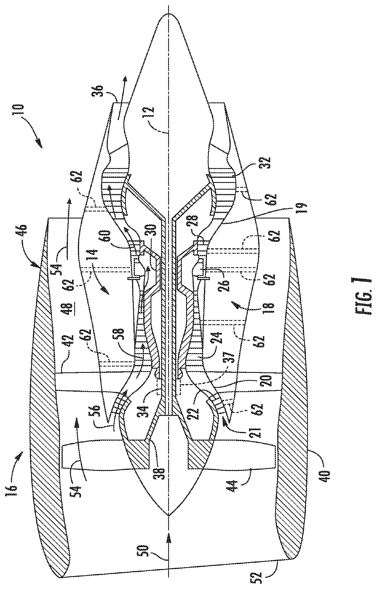
[0033]Reference now will be made in detail to embodiments of the invention, one or more examples of which are illustrated in the drawings. Each example is provided by way of explanation of the invention, not limitation of the invention. In fact, it will be apparent to those skilled in the art that various modifications and variations can be made in the present invention without departing from the scope or spirit of the invention. For instance, features illustrated or described as part of one embodiment can be used with another embodiment to yield a still further embodiment. Thus, it is intended that the present invention covers such modifications and variations as come within the scope of the appended claims and their equivalents.

[0034]As used herein, the terms “first”, “second”, and “third” may be used interchangeably to distinguish one component from another and are not intended to signify location or importance of the individual components.

[0035]The terms “upstream” and “downstre...


PUM

PropertyMeasurementUnit
lengthaaaaaaaaaa
rigidityaaaaaaaaaa
pressureaaaaaaaaaa

Abstract

Systems for inserting and orienting a soft robotic probe into an apparatus and capturing images and methods of using the same are generally disclosed. For example, the system includes a cable, an actuation assembly, and a camera at the tip of the probe. The cable includes an adjustable sheath at an exterior of the cable defined around a probe centerline extending the length of the probe. The adjustable sheath extends and contracts the cable between a first length and a second length different from the first length and is defined within the adjustable sheath. The actuation assembly extends or contracts the cable between the first length and the second length and further adjusts an orientation of the cable, an orientation of the tip of the probe, or both along at least one axis. The camera captures images at least partially around a circumferential direction relative to a camera centerline.

Description

FIELD[0001]The present subject matter relates generally to a probe for inspection of an apparatus, and more particularly to a system and method for automated soft robotic probe insertion into an apparatus.BACKGROUND[0002]Optical scopes are used as an inspection tool to view inside an apparatus such as a turbomachine or engine. Optical scopes, such as borescopes, include a removable optical adapter tip at an end of the optical scope. The optical adapter is generally suited for various purposes, such as providing a discrete direction of view. The optical scope, including the optical adapter, is ingressed into the apparatus for viewing and assessing internal components.[0003]In order to allow for periodic inspection of internal parts of the engine (e.g., blades, vanes, shrouds, disks, frames, etc.), borescope ports are typically provided in the engine casings and / or frames. Such ports allow optical borescope instruments to be inserted into the core engine to enable a visual inspection ...

Claims


Application Information

Patent Timeline
Patent Type & Authority Patents(United States)
IPC IPC(8): G01N21/88G01N21/954
CPCG01N21/954G01N21/8806G01N2021/9546G01N2021/9544
Inventor MEKALA, RAJESHRAO, BELLARY MADHUSUDANCHAUGULE, VINAYCORONA, ILEANA PRISABELREYES, RAMONVILLARREAL, RAMON ULISESSETHURAMAN, RAMAKRISHNAN
Owner GENERAL ELECTRIC CO
Learn More