Arrangement of stack spark gaps and device for holding together and electrically contacting stack spark gaps

a technology of stack spark gap and stack spark gap, which is applied in the direction of emergency protective arrangements, mechanical devices, fastening means, etc., can solve the problem of limited number of individual electrodes of stack spark gap

Active Publication Date: 2020-09-15
PHOENIX CONTACT GMBH & CO KG
View PDF17 Cites 0 Cited by
  • Summary
  • Abstract
  • Description
  • Claims
  • Application Information

AI Technical Summary

Benefits of technology

[0010]It is especially advantageous for a user when not all three connection elements of the stack spark gaps are arranged on one side of the arrangement. In particular, such an arrangement is advantageous in which two connection elements are on one side of the arrangement and one connection element is on the opposite side of the arrangement. A preferred configuration of the arrangement according to the invention is accordingly further wherein the stack spark gaps are arranged between the clamping elements in such a way that the connection sides of two stack spark gaps are facing the first clamping element, and the connection side of the third stack spark gap is facing the second clamping element. The front ends of two stack spark gaps that are opposite to the connection sides are then connected to the second clamping element in an electrically conductive manner, and the front end of the third stack spark gap that is opposite to the connection side is then connected to the first clamping element in an electrically conductive manner. Furthermore, it is especially advantageous when the two outer stack spark gaps are arranged identically. Accordingly, the center stack spark gap is preferably the third stack spark gap, which is insulated electrically from the first clamping element and which is connected to the second clamping element in an electrically conductive manner via the front end that is opposite to the connection side. In this way, the distance between the two connection elements that are arranged on one side of the arrangement can be kept as large as possible.
[0012]In this way, an especially simple installation of the arrangement is possible.
[0024]An especially advantageous configuration of the device according to the invention is distinguished in such a way that the two insulators that are arranged on the first clamping element are produced by a common first insulating element. The insulator that is arranged on the second clamping element is produced by a second insulating element. In this way, the installation cost is reduced, since fewer parts have to be installed, when two insulators are produced by a single insulating element.

Problems solved by technology

It is disadvantageous in the known arrangement that tensile forces that arise in the case of overvoltage have to be taken up by the housing, which results in twisting.
Moreover, the number of individual electrodes of a stack spark gap is limited by the size of the recesses in the plastic housing, in which the stack spark gaps are accommodated.

Method used


Image

  • Arrangement of stack spark gaps and device for holding together and electrically contacting stack spark gaps
  • Arrangement of stack spark gaps and device for holding together and electrically contacting stack spark gaps
  • Arrangement of stack spark gaps and device for holding together and electrically contacting stack spark gaps

Examples


Embodiment Construction

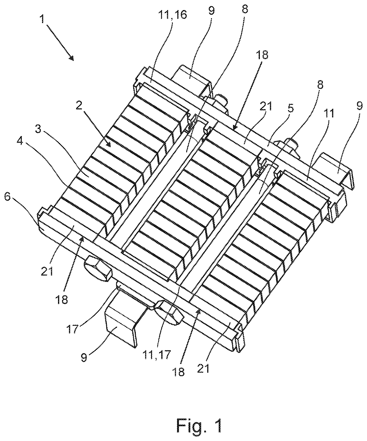
[0037]FIG. 1 shows a sectional view through an arrangement 1 of stack spark gaps 2. The arrangement 1 comprises three stack spark gaps 2, whereby each stack spark gap 2 is built up of multiple electrodes 3 and insulating elements 4 that are arranged between the electrodes 3. The stack spark gaps 2 are clamped between a first clamping element 5 and a second clamping element 6. Moreover, the stack spark gaps 2 are arranged beside one another in a parallel manner. The two clamping elements 5, 6 are arranged opposite to one another on the ends 7 (FIG. 5) of the stack spark gaps 2 and are also connected to one another via connecting elements 8. In the perspective view, two connecting elements 8 are visible. The clamping elements 5, 6 and the connecting elements 8 are electrically conductive, in such a way that the two clamping elements 5, 6 are connected to one another electrically via the connecting elements 8.

[0038]Each stack spark gap 2 can be connected via a connection element 9, whe...


PUM


Abstract

An arrangement of stack spark gaps, whereby a stack spark gap has multiple electrodes and insulating elements that are arranged between the electrodes, with a first electrically conductive clamping element and a second electrically conductive clamping element, whereby the two clamping elements are arranged opposite to the front ends of the stack spark gaps, with at least one connecting element, by which the two clamping elements are connected to one another, and with connection elements for electrical connection to the stack spark gaps. A device is provided for holding the stack spark gaps together and having them make contact. Three stack spark gaps are arranged beside one another between the two clamping elements, at least one of which is electrically conductive, and the two clamping elements are connected to one another electrically via the connecting element and are arranged with the spark gaps so as to form a star circuit.

Description

BACKGROUND OF THE INVENTIONField of the Invention[0001]The invention relates to an arrangement of stack spark gaps, whereby a stack spark gap has multiple electrodes and insulating elements that are arranged between the electrodes, with a first electrically conductive clamping element and a second electrically conductive clamping element, whereby the two clamping elements are arranged opposite to the front ends of the stack spark gaps, with at least one connecting element, by which the two clamping elements are connected to one another, and with connection elements for electrical connection of the stack spark gaps. In addition, the invention relates to a device for holding stack spark gaps together and having them make contact.Description of the Related Art[0002]Stack spark gaps per se have been known for many years from the state of the art, typically from the area of surge protection. Here, the stack spark gaps provide the surge diverter, which when a threshold voltage is exceeded...

Claims


Application Information

Patent Timeline
Patent Type & Authority Patents(United States)
IPC IPC(8): H02H9/06H01T4/18H01T4/06H01R4/38
CPCH01R4/38H01T4/18H01T4/06H02H9/06H01T4/16F16B2/065
Inventor MEYER, THOMASSAGEBIEL, HANNES
Owner PHOENIX CONTACT GMBH & CO KG
Why Eureka
Try Eureka