
Sensor device

a technology of sensor and mounting step, which is applied in the direction of measurement devices, instruments, transportation and packaging, etc., can solve the problems of difficult to secure a mounting space, difficult to reduce the number of components and mounting steps, etc., and achieve the effect of reducing the number of mounting steps, reducing the number of components and the number of mounting steps

Active Publication Date: 2020-10-06
JTEKT CORP
View PDF13 Cites 0 Cited by
  • Summary
  • Abstract
  • Description
  • Claims
  • Application Information

AI Technical Summary

Benefits of technology

[0009]It is one object of the present invention to provide a sensor device in which the number of components and the number of mounting steps can be reduced, whereby the cost can be reduced. It is another object of the present invention to provide a sensor device in which the mountability on a mounting target such as a vehicle is improved.

Problems solved by technology

Therefore, it is difficult to reduce the number of components and the number of mounting steps.
Therefore, it may be difficult to secure a mounting space while avoiding interference with other on-board devices or the like.

Method used


Image

  • Sensor device
  • Sensor device
  • Sensor device

Examples


Embodiment Construction

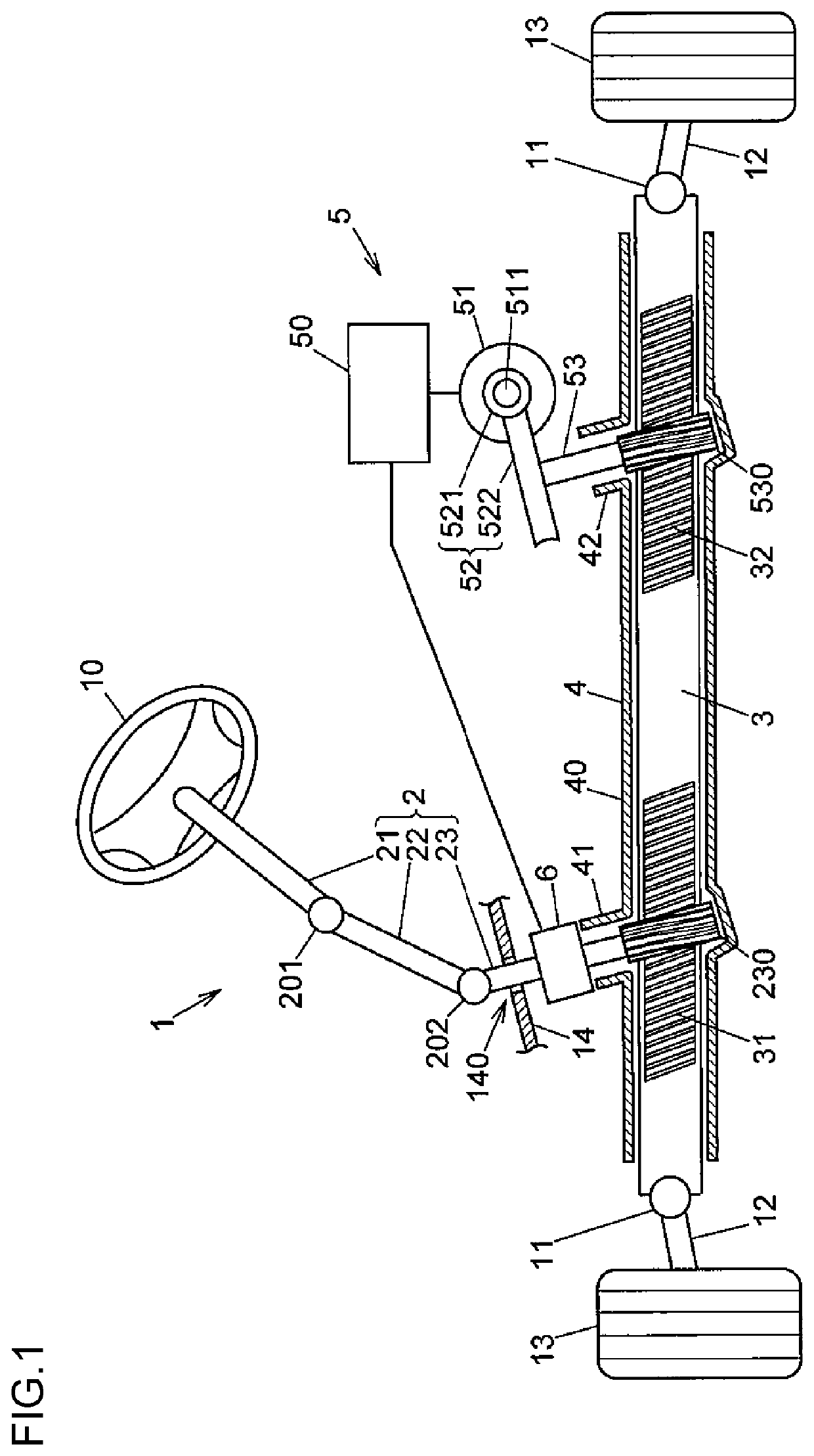
[0021]An embodiment of the present invention is described below with reference to the drawings. FIG. 1 is a structural view schematically illustrating an example of the structure of a steering system including a sensor device according to the embodiment of the present invention.

[0022]A steering system 1 includes a steering wheel 10, a column shaft 21, an intermediate shaft 22, a first pinion shaft 23, a rack shaft 3, a rack housing 4, a steering assist device 5, and a sensor device 6. The steering wheel 10 is operated to rotate by a driver. The steering wheel 10 is fixed to one end of the column shaft 21. The intermediate shaft 22 is coupled to the column shaft 21 via a universal joint 201. The first pinion shaft 23 is coupled to the intermediate shaft 22 via a universal joint 202. The rack shaft 3 serves as a steering operation shaft that meshes with the first pinion shaft 23. The rack housing 4 houses the rack shaft 3, and extends in a vehicle width direction. The steering assist ...


PUM

PropertyMeasurementUnit
flexibleaaaaaaaaaa
rotation angleaaaaaaaaaa
soft magneticaaaaaaaaaa

Abstract

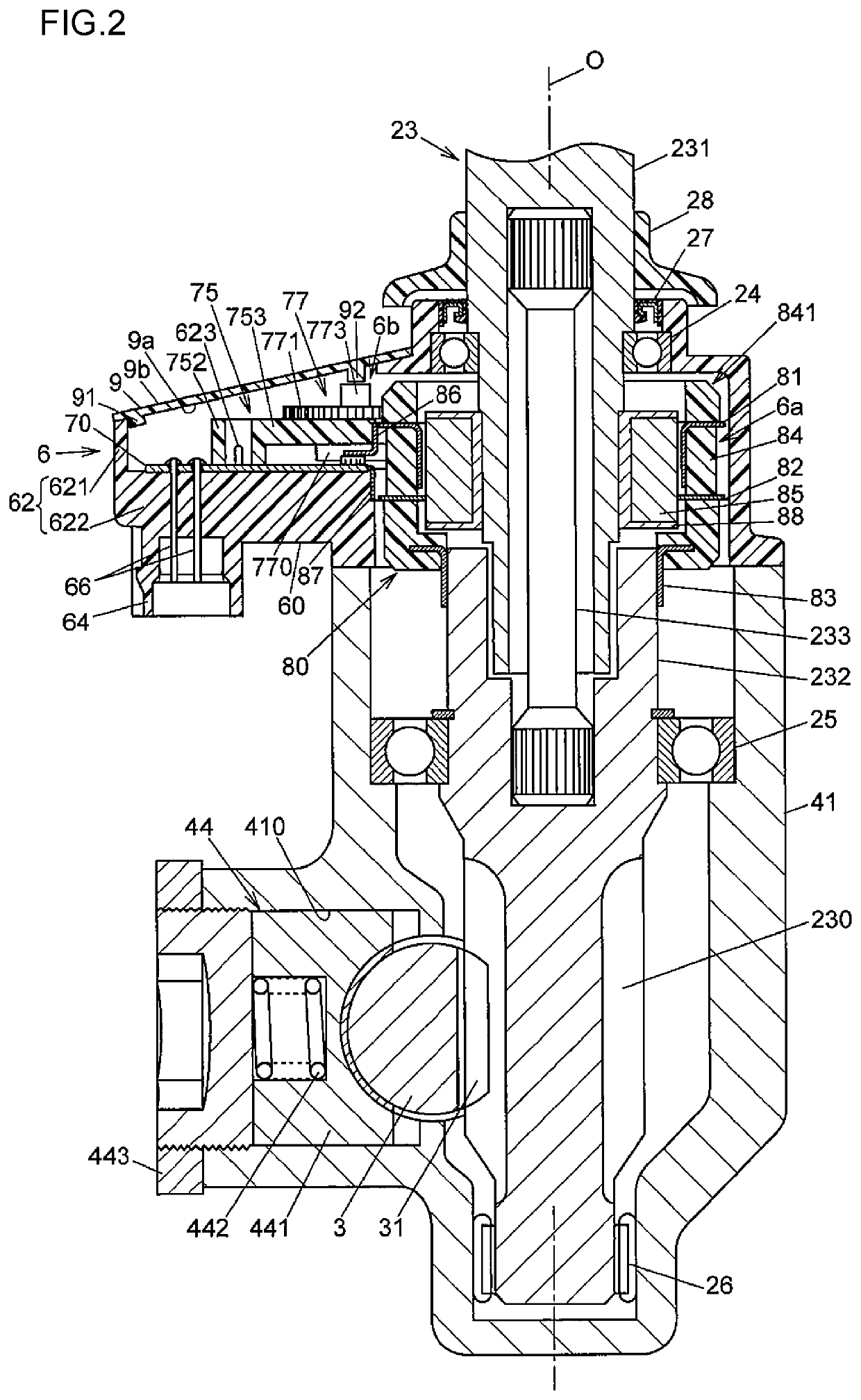
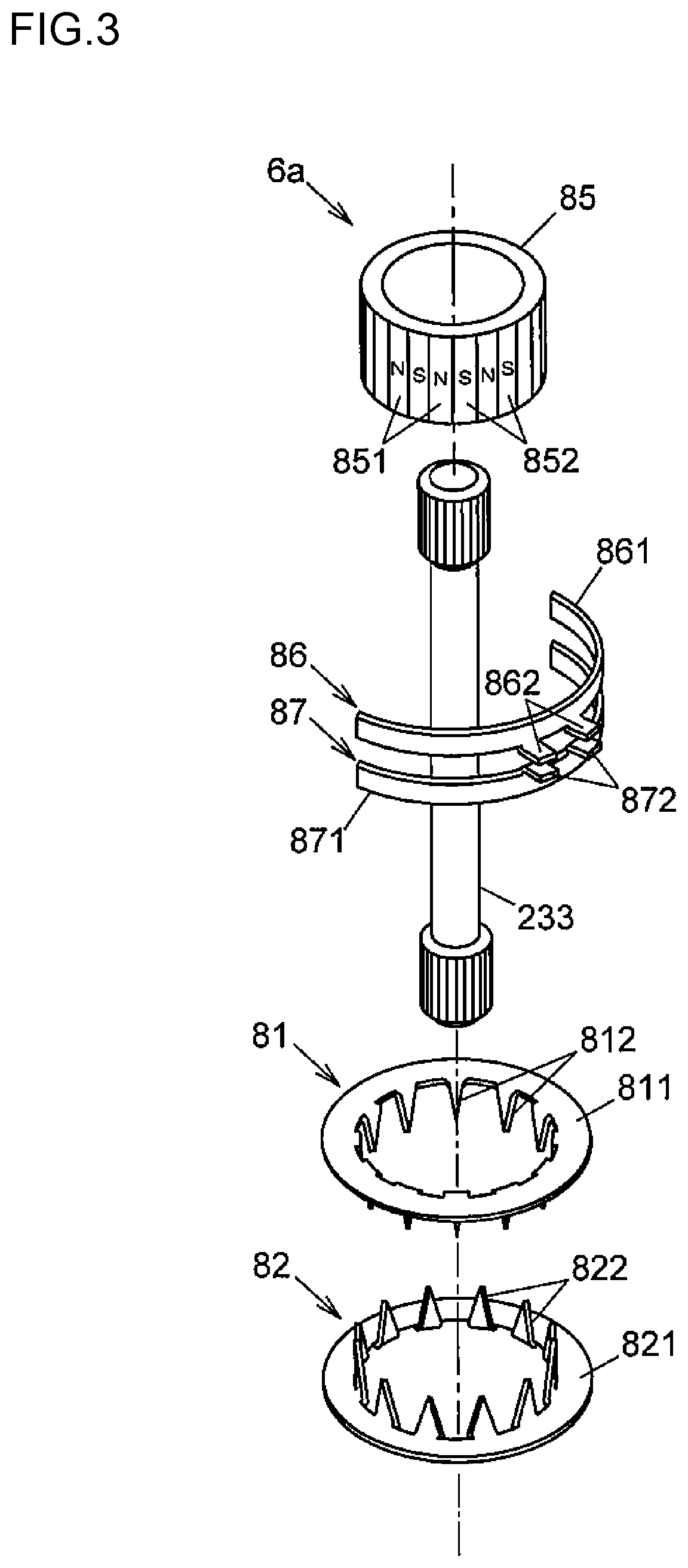
A sensor device where the number of components and mounting steps can be reduced and mountability on a mounting target is improved. A sensor device configured to detect a torque applied to a pinion shaft and pinion shaft's rotation angle. The pinion shaft is formed by coupling an input shaft and output shaft together by a torsion bar. The sensor device includes a torque detecting portion wherein magnetic fields detected by torque detection magnetic sensors change based on the torsion bar's twisting amount, a rotation angle detecting portion wherein magnetic fields detected by rotation angle detection magnetic sensors change based on the pinion shaft's rotation angle, a housing that houses the torque detecting portion and the rotation angle detecting portion, and a circuit board held by the housing. Both the torque detection magnetic sensors and the rotation angle detection magnetic sensors are mounted on the circuit board.

Description

INCORPORATION BY REFERENCE[0001]The disclosure of Japanese Patent Application No. 2017-199463 filed on Oct. 13, 2017 including the specification, drawings and abstract, is incorporated herein by reference in its entirety.BACKGROUND OF THE INVENTION1. Field of the Invention[0002]The present invention relates to a sensor device whose detection target is a shaft formed by coupling a pair of rotation shaft members together by a flexible torsion shaft, and which is configured to detect a torque applied to the shaft and a rotation angle of the shaft.2. Description of the Related Art[0003]Hitherto, a sensor device configured to detect a torque and a rotation angle of a shaft formed by coupling a pair of rotation shaft members together by a flexible torsion shaft is used in, for example, a steering system of a vehicle (see, for example, Japanese Patent Application Publication No. 2013-92461 (JP 2013-92461 A)).[0004]In the steering system described in JP 2013-92461 A, a column shaft is inser...

Claims


Application Information

Patent Timeline
Patent Type & Authority Patents(United States)
IPC IPC(8): G01L3/10
CPCG01L3/104B62D1/16B62D15/00B62D15/0215
Inventor TOYAMA, YUICHI
Owner JTEKT CORP
Learn More