
Snow plow assembly with floating a-frame

a technology of a frame and a snow plow, which is applied in the field of snow plows, can solve the problems of significant stress and wear on the snow plow assembly, unremoved snow from the ground, etc., and achieve the effect of improving snow removal

Active Publication Date: 2020-10-13
BUYERS PRODS
View PDF23 Cites 3 Cited by
  • Summary
  • Abstract
  • Description
  • Claims
  • Application Information

AI Technical Summary

Benefits of technology

The present invention provides a snow plow assembly with a push frame, lift frame, and coupling that allows the push frame to float vertically relative to the lift frame and rotate about a longitudinal axis to accommodate for irregular or uneven ground surfaces. The coupling includes a bearing block and retaining member that distribute load on the push frame to reduce wear and tear. The snow plow assembly also includes a mounting bar, A-frame, lift frame, and first and second couplings that allow the push frame to float vertically and independently relative to the lift frame. The technical effects of the invention include improved snow removal, reduced wear on the push frame, and improved durability of the snow plow assembly.

Problems solved by technology

During the use of such snow plow assemblies, the vehicle and / or snow plow assembly may travel over irregular or uneven ground surfaces, which may cause uneven removal of snow from the ground.
In addition, the snow plow assembly may experience a significant amount of pushing and pulling force during normal use, which can cause a significant amount of stress and wear on the snow plow assembly.

Method used


Image

  • Snow plow assembly with floating a-frame
  • Snow plow assembly with floating a-frame
  • Snow plow assembly with floating a-frame

Examples


Embodiment Construction

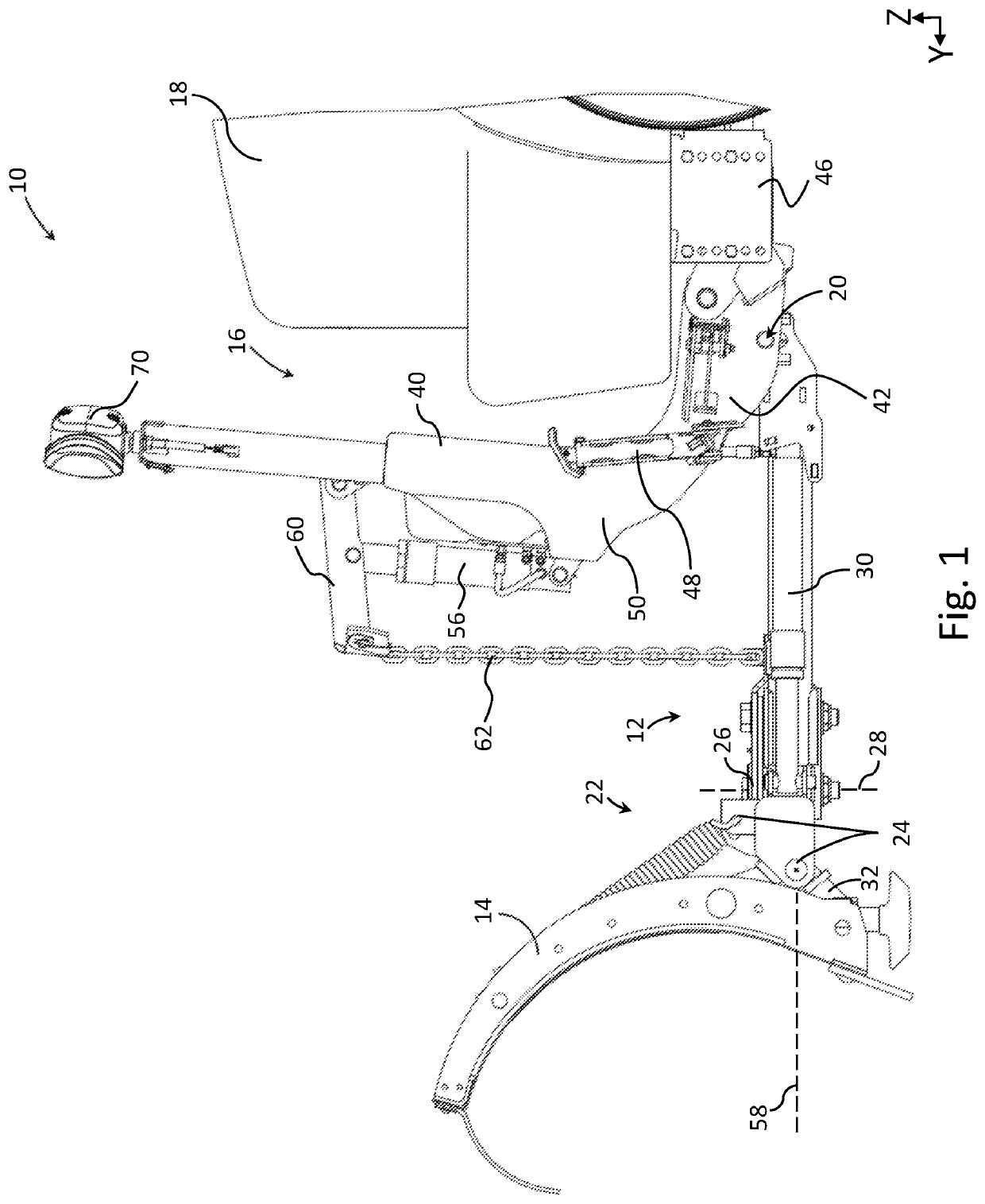
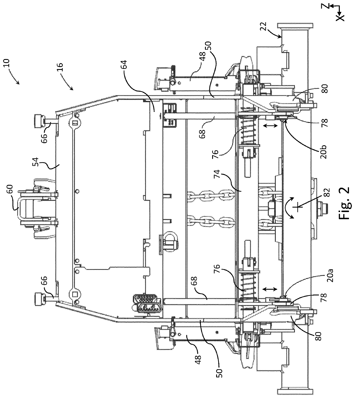
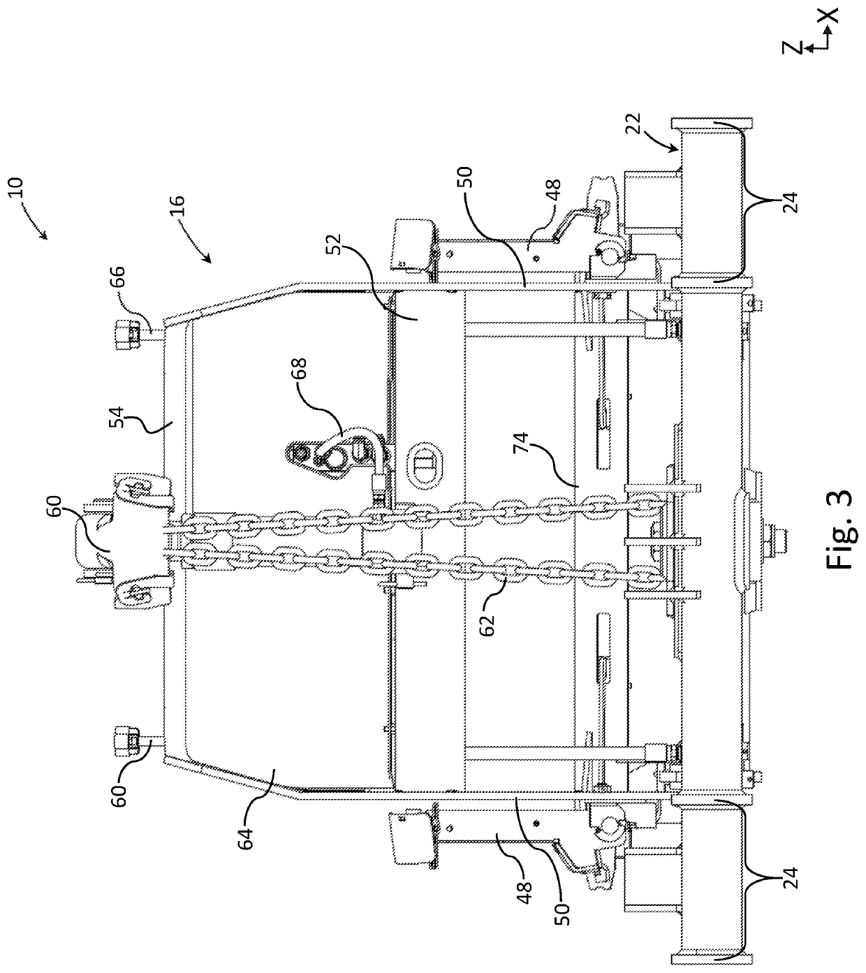
[0021]The principles of the present invention have particular application to snow plow assemblies for a vehicle, including commercial, residential, or all-purpose vehicles, and will be described below chiefly in this context. It is also understood, however, that the principles of the present invention may be applicable to other plow assemblies or vehicle-mounted accessories for other applications where it is desirable to provide one or more couplings that allow a push frame to be floatably coupled to a lift frame for accommodating irregular or uneven ground surfaces; and / or where it is desirable to provide one or more bearing blocks in the coupling to improve the load distribution on the push frame to reduce wear.

[0022]In the discussion above and to follow, the terms “upper”, “lower”, “top”, “bottom,”“inner,”“outer,”“left,”“right,”“above,”“below,”“horizontal,”“vertical,” etc. refer to the snow plow assembly as viewed in a horizontal position, as shown in FIG. 1, for example. As gene...


PUM


Abstract

A snow plow assembly having a push frame, a lift frame, and a coupling configured to floatably attach the push frame to a lift frame. The coupling may attach the left and right sides of the push frame to the corresponding left and right sides of the lift frame, and each coupling may be independently vertically floatable to allow the push frame to float vertically relative to the lift frame, while also allowing the push frame to rotate relative to the lift frame to accommodate for irregular or uneven ground surfaces. The couplings may each include a retaining member for operatively coupling the push frame to the lift frame, and one or more bearing blocks that facilitate distribution of load between the push frame and retaining member to reduce wear on the push frame. The bearing blocks also may be vertically movable relative to the push frame for common vertical movement with the retaining members to enable such floating movement.

Description

FIELD OF INVENTION[0001]The present invention relates generally to snow plows, and more particularly to snow plow assemblies having a floating A-frame.BACKGROUND[0002]Snow plow assemblies are used on commercial, residential, or all-purpose vehicles for the effective removal of snow from the ground. A typical snow plow assembly includes a mounting frame coupled to a moldboard assembly for plowing the snow, a push frame pivotably connected to the mounting frame for allowing lateral pivoting movement of the mounting frame and moldboard assembly, and a lift frame operatively coupled to the push frame for vertically raising or lowering the push frame and the mounting frame. During the use of such snow plow assemblies, the vehicle and / or snow plow assembly may travel over irregular or uneven ground surfaces, which may cause uneven removal of snow from the ground. In addition, the snow plow assembly may experience a significant amount of pushing and pulling force during normal use, which c...

Claims


Application Information

Patent Timeline
Patent Type & Authority Patents(United States)
IPC IPC(8): E01H5/06
CPCE01H5/066
Inventor MOORMAN, SCOTT
Owner BUYERS PRODS
Learn More