Sheet supplying apparatus and printing apparatus

a technology of supplying apparatus and printing apparatus, which is applied in the direction of printing, thin material processing, function indicators, etc., can solve the problem that the automatic feeding of sheets may not work smoothly

Active Publication Date: 2020-11-10
CANON KK
View PDF21 Cites 3 Cited by
  • Summary
  • Abstract
  • Description
  • Claims
  • Application Information

AI Technical Summary

Benefits of technology

[0004]It is an object of the present invention to provide a sheet supplying apparatus and a printing apparatus which are capable of winding the roll set by a user tightly.

Problems solved by technology

In a case in which the roll set in a sheet supplying apparatus is not tightly wound, the automatic sheet feeding may not work smoothly since the roll is loose.

Method used


Image

  • Sheet supplying apparatus and printing apparatus
  • Sheet supplying apparatus and printing apparatus
  • Sheet supplying apparatus and printing apparatus

Examples


first embodiment

[0039]An embodiment of the leading end portion setting process (step S3 in FIG. 6) executed by the printing apparatus 100 will be described below. In the present embodiment, at the time of the leading end portion setting process, the loose roll R is tightened and wound tightly without intervention of the user.

[0040]A basic procedure of winding tightly is as follows. The roll is caused to perform more than one rotation in the opposite direction (the direction of arrow C2) prior to the sheet feeding operation. During the time, the roll is caused to rotate in the opposite direction continuously until a detection cycle in which the sensor detects the sheet leading end portion twice or more falls within a predetermined allowable range. With this operation, the roll R is tightly wound on the apparatus, and thus the loose roll R is tightened. After this operation, the automatic sheet feeding is performed. This will be described in detail below.

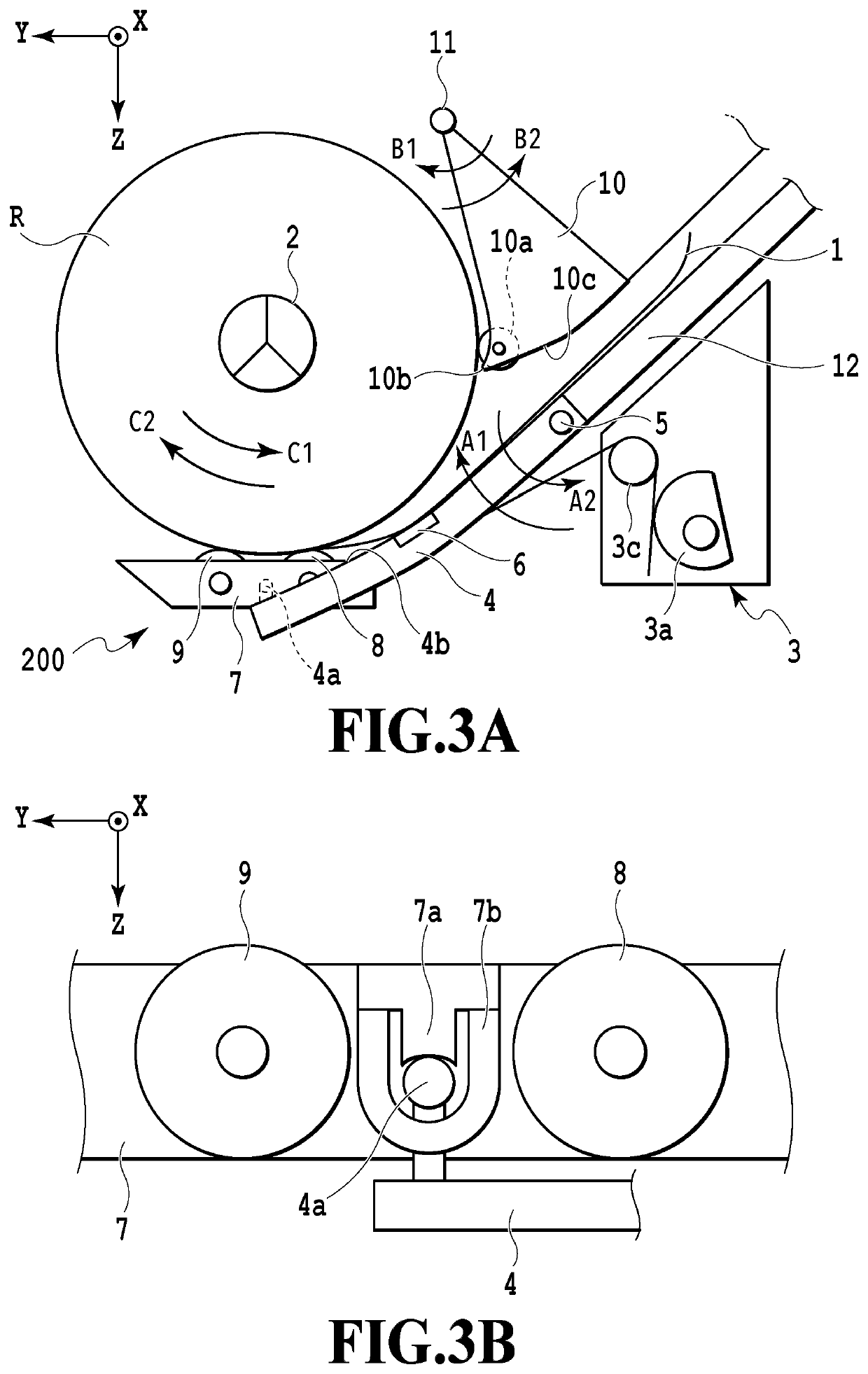
[0041]The sensor unit 6 according to the prese...

modified example

[0061]As the sensor unit 6, a distance sensor other than an optical sensor can be used as long as the sensor has an output value changing according to a distance to the sheet. For example, a distance sensor such as an ultrasonic sensor or an electrostatic sensor that detects the distance to the object in a non-contact manner can be used.

[0062]The printing apparatus is not limited to the configuration including the two sheet supplying apparatuses corresponding to the two roll sheets and may be a configuration including one sheet supplying apparatus or three or more sheet supplying apparatuses. Further, the printing apparatus is not limited to only the inkjet printing apparatus as long as an image can be printed on a sheet supplied from the sheet supplying apparatus. Further, the printing system and configuration of the printing apparatus are arbitrary as well. For example, a serial scan system of repeating scanning of the print head and the sheet conveyance operation and printing an ...


PUM

PropertyMeasurementUnit
rotational angleaaaaaaaaaa
angleaaaaaaaaaa

Abstract

A sheet supplying apparatus, which is capable of winding a sheet tightly, includes a driving unit configured to cause a roll including a wound consecutive sheet to rotate in a first direction for feeding the sheet or a second direction opposite to the first direction, a sensor that detects a leading end portion of the sheet separated from an outer circumferential surface of the roll, and a contact body that presses the outer circumferential surface. Before the sheet is fed, in a state in which the contact body presses the outer circumferential surface, the driving unit causes the roll to continuously rotate in the second direction until a detection cycle of the leading end portion by the sensor is less than a predetermined value.

Description

BACKGROUND OF THE INVENTIONField of the Invention[0001]The present invention relates to a sheet supplying apparatus and a printing apparatus which are capable of pulling a sheet out of a roll on which a continuous sheet is wound and supplying the sheet.Description of the Related Art[0002]A printing apparatus that detects a sheet leading end of an installed roll sheet (hereinafter also referred to simply as a “roll”) and automatically feeds the sheet is disclosed in Japanese Patent Laid-Open No. 2011-37557. In this apparatus, the sheet leading end is detected through an optical sensor while causing the roll to rotate in a winding direction opposite to a supply direction, and when the detection is completed, the roll is caused to rotate in the supply direction, and the sheet separated from the roll (hereinafter also referred to as “peeling”) is fed to the inside of the apparatus.SUMMARY OF THE INVENTION[0003]In a case in which the roll set in a sheet supplying apparatus is not tightly...

Claims


Application Information

Patent Timeline
Patent Type & Authority Patents(United States)
IPC IPC(8): B65H23/04B41J11/66B41J11/00B65H23/182B41J11/02B65H16/10B65H20/02
CPCB65H23/042B41J11/0045B41J11/0095B65H20/02B65H23/1825B41J11/02B41J11/66B65H16/106B65H2701/1311B65H2403/942B65H2301/522B65H2220/01B65H2220/02B65H2220/03B65H19/105
Inventor SUZUKI, TOMOHIROKAMADA, MASASHIEIYAMA, MASATOIGARASHI, YUKINEGISHI, MASASHISHINJO, RYOYAKOBAYASHI, RYO
Owner CANON KK
Why Eureka
Try Eureka