Apparatus for orienting a guide vane support relative to a turbine casing

a technology for orienting apparatus and guide vane, which is applied in the direction of mechanical apparatus, engine components, machines/engines, etc., can solve the problems of particular limited length of adjusting elements, achieve simple and cost-effective production, reduce the number of individual parts, and reduce production and installation costs

Active Publication Date: 2020-12-15
SIEMENS ENERGY GLOBAL GMBH & CO KG
View PDF47 Cites 0 Cited by
  • Summary
  • Abstract
  • Description
  • Claims
  • Application Information

AI Technical Summary

Benefits of technology

[0015]The advantage of the invention lies in particular in the fact that one guide device makes it possible to carry out two adjustment processes, and the adjusting elements used for this purpose can be secured against shifting of the adjustment by means of a single securing device. Furthermore, the apparatus is simple and cost-effective to produce and requires, in comparison to conventional apparatus, a greatly reduced number of individual parts. This permits simple adjustment of guide vane carriers relative to the casing, and lowers both production and installation costs.
[0016]In one advantageous embodiment of the invention, an adjustment means is arranged between the first adjusting element and the support surface of the recess. The adjustment means is advantageously disk-shaped. A contact surface of the adjustment means, oriented toward the first adjusting element, advantageously corresponds essentially to a negative of the corresponding surface of the first adjustment means. The adjustment means advantageously has a semicircular cross-sectional area. This ensures an evenly distributed transfer of forces, even in the event of relative pivoting between the guide vane carrier and the casing.
[0017]Advantageously, a contact surface between the first adjusting element and the adjustment means is essentially spherical. In that context, it is advantageous if the adjustment means has a convex contact surface and the first adjusting element has a concave contact surface. Pairing a convex surface with a corresponding concave surface makes it possible to pivot the guide vane carrier about two axes relative to the casing.
[0018]In one embodiment, the apparatus has a first screw for attaching the guide device to the guide vane carrier. The first screw prevents the guide device coming loose from the recess when the turbine cools down.
[0019]According to another embodiment, the first region can be arranged with a form fit in the recess. A form fit reliably prevents relative movement between the guide device and the guide vane carrier, while a force-fitting connection, e.g. by means of seating phenomena, cannot always prevent such relative movements.
[0020]It is advantageous that the first adjusting element has a form-fitting section for the engagement of an installation tool that is guided through the guide channel. This permits adjustment of the guide vane carrier relative to the casing even in the installed state. In that context, the second adjusting element is advantageously not yet arranged in the guide channel. Alternatively, the second adjusting element can have a passage for a corresponding tool, such that the second adjusting element can be arranged in the guide channel even during adjustment by means of the first adjusting element.

Problems solved by technology

The length of the adjusting elements is in particular limited by the fact that an adjusting element must not hamper adjustment of the respective other adjusting element.

Method used


Image

  • Apparatus for orienting a guide vane support relative to a turbine casing

Examples


Embodiment Construction

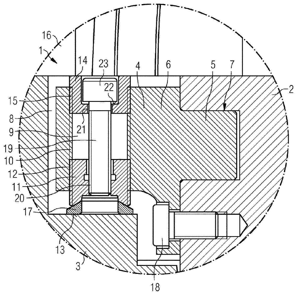
[0027]FIG. 1 shows an apparatus 1 according to the invention in longitudinal section. The apparatus 1 has a guide device 4 with a first region 5 and a second region 6. The first region 5 is arranged with a form fit in a recess 7 of a receiving web of a guide vane carrier 2, and is attached thereto by means of a first screw 18.

[0028]The second region 6 is arranged in a recess 8 of a casing 3 and has a guide channel 9 with a continuous first internal thread 10. Alternatively, it is also possible for the first internal thread 10 to be interrupted, in particular in a central section.

[0029]A first adjusting element 11 with a first external thread 12 is arranged in a lower (in this representation) region of the guide channel 9 such that the first external thread 12 is in engagement with the first internal thread 10. The first adjusting element 11 has an essentially cylindrical main body which is cap-shaped on a bearing side. The bearing side is arranged on a part-spherical contact side of...


PUM


Abstract

An apparatus and method for orienting a guide vane carrier relative to a turbine casing. The apparatus has a guide device with a first region and a second region, wherein the first region is arranged in a recess of the guide vane carrier and the second region is arranged in a recess of the casing. The second region of the guide device has a guide channel with a first internal thread, wherein a first adjusting element with a first external thread is arranged in the guide channel. The first external thread can be screwed together with the first internal thread. The first adjusting element can be arranged in the guide channel such that, when the guide device is supported against a support surface of the recess, a force flow runs through the first adjusting element from the recess to the guide device.

Description

CROSS REFERENCE TO RELATED APPLICATIONS[0001]This application is the US National Stage of International Application No. PCT / EP2015 / 060303 filed May 11, 2015, and claims the benefit thereof. The International Application claims the benefit of German Application No. DE 102014214703.4 filed Jul. 25, 2014. All of the applications are incorporated by reference herein in their entirety.FIELD OF INVENTION[0002]The present invention relates to an apparatus for orienting a guide vane carrier relative to a turbine casing. The invention relates in particular to such an apparatus, having a guide device with a first region and a second region, wherein the first region is arranged in a recess of the guide vane carrier and the second region is arranged in a recess of the casing. The second region of the guide device has a guide channel with a first internal thread, wherein a first adjusting element with a first external thread is arranged in the guide channel. The first external thread can be scre...

Claims


Application Information

Patent Timeline
Patent Type & Authority Patents(United States)
IPC IPC(8): F01D25/24F01D25/28
CPCF01D25/28F01D25/246F05D2230/60
Inventor LOCHNER, KLAUSMUCHA, ANDREAS
Owner SIEMENS ENERGY GLOBAL GMBH & CO KG
Why Eureka
Try Eureka