DC generator system

a technology of dc generator and torque ripple, which is applied in the direction of electric generator control, control system, aircraft power plants, etc., can solve the problems of reducing lru efficiencies, contactor control, and system performance parameters produced by ripple on the bus, so as to reduce voltage ripple and load ripple

Active Publication Date: 2020-12-15
HAMILTON SUNDSTRAND CORP
View PDF17 Cites 0 Cited by
  • Summary
  • Abstract
  • Description
  • Claims
  • Application Information

AI Technical Summary

Benefits of technology

[0007]A method includes driving alternating current from a first generator connected to a low pressure gearbox spool, driving alternating current from a second generator connected to a high pressure gearbox spool, and aligning a frequency output of the first generator to a frequency output of the second generator in order to control performance parameters of a direct current system of an aircraft, comprising reducing voltage ripple and reducing load ripple.

Problems solved by technology

In High Voltage DC, such as 540 volts, parallel applications, DC voltage ripple on the bus produces unacceptable system performance parameters, such as reduced LRU efficiencies, torque ripple, load ripple and contactor control issues, and reduced overall system reliability.
Conventional methods and systems have generally been considered unsatisfactory for their intended purpose of controlling and reducing torque ripple in the aforementioned systems.

Method used


Image

  • DC generator system

Examples


Embodiment Construction

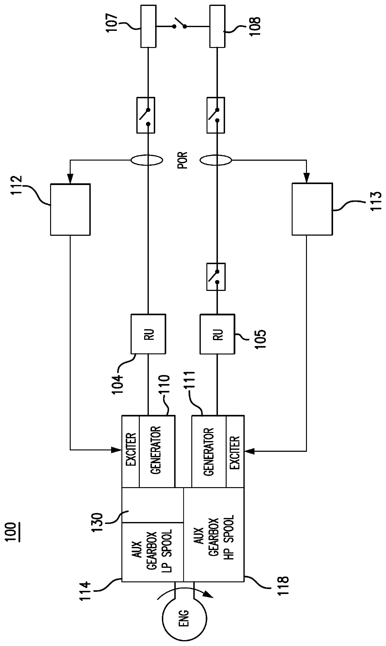
[0011]Reference will now be made to the drawings wherein like reference numerals identify similar structural features or aspects of the subject invention. For purposes of explanation and illustration, and not limitation, a partial view of an exemplary embodiment of a direct current generation system in accordance with the disclosure is shown in FIG. 1 and is designated generally by reference character 100. The methods and systems of the disclosure can be used to decrease the bus voltage ripple, which in turn improves system efficiencies.

[0012]FIG. 1 shows a variable frequency generator (VFG) 102 configured to direct alternating current to a first rectifier 104, which is configured to convert alternating current from a generator 110 to direct current and drive it to an HVDC Bus Network 106 responsible for distributing power to various aircraft components. A variable frequency second generator (VFG) 103 is shown including a second generator 111 configured to direct alternating current...


PUM


Abstract

A system including a variable frequency generator (VFG) including a generator configured to conduct alternating current to a first rectifier configured to convert alternating current from the VFG to direct current and drive it to an HVDC Bus Network, a variable frequency second generator including a second generator configured to conduct alternating current to a second rectifier configured to convert alternating current from the second generator to direct current and conduct it to the HVDC Bus Network, a speed correcting gearbox operatively connected to the VFG configured to align generator frequency to the second generator frequency, and a VFG control unit operatively connected to the generator configured to control the VFG, and a second generator control unit operatively connected to the second generator and the HVDC Bus Network configured to control the second generator.

Description

BACKGROUNDTechnological Field[0001]The present disclosure relates to managing electrical system, and more particularly to reducing torque ripple in electrical power generation systems.Description of Related Art[0002]In High Voltage DC, such as 540 volts, parallel applications, DC voltage ripple on the bus produces unacceptable system performance parameters, such as reduced LRU efficiencies, torque ripple, load ripple and contactor control issues, and reduced overall system reliability.[0003]Conventional methods and systems have generally been considered unsatisfactory for their intended purpose of controlling and reducing torque ripple in the aforementioned systems. There is a need in the art for electrical management systems having reduced torque ripple and reduced load ripple. There also remains a need in the art for such systems that are economically viable. The present disclosure may provide a solution for at least one of these remaining challenges.SUMMARY OF THE INVENTION[0004]...

Claims


Application Information

Patent Timeline
Patent Type & Authority Patents(United States)
IPC IPC(8): H02P9/10H02P9/30B64D31/00H02P101/25H02P101/30
CPCB64D31/00H02P9/102H02P9/307H02P2101/25B64D2221/00H02P2101/30H02P9/00
Inventor LEGROS, CRAIG R.UTECHT, TOM A.
Owner HAMILTON SUNDSTRAND CORP
Why Eureka
Try Eureka